


Fluid Supply
18 3A1163A
Fluid Supply
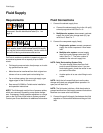
Requirements
ProControl models are available to operate air spray or
air-assisted systems with a capacity of up to 3800
cc/min.
• Fluid supply pressure tanks, feed pumps, or circulat-
ing systems can be used.
• Materials can be transferred from their original con-
tainers or from a central paint recirculating line.
• For an airless system, the user must supply a gun
trigger signal to the ProControl 1KS.
• See manual 313599 for Coriolis meter installation
and operation instructions.
NOTE: The fluid supply must be free of pressure spikes,
which are commonly caused by pump stroke change-
over. If necessary, install pressure regulators or a surge
tank on the ProControl fluid inlets to reduce pulsation.
Contact your Graco distributor for additional information.
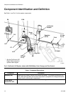
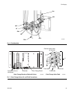
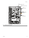
Fluid Connections
1. Connect the solvent supply lines.
a. Connect the solvent supply line to the 1/4 npt(f)
solvent purge valve inlet. See F
IG. 6.
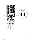
b. Multiple color system: also connect a solvent
supply line to the color change stack (Q), top
valve 4 or 5. See F
IG. 7.
2. Connect the component supply line(s).
➜ Single color system: connect component
supply line to the component A flow meter
inlet.
➜ Multiple color system: connect supply
lines to the color change valve stack (S)
inlets. See F
IG. 7. The color number is
marked on the valve air supply line.
NOTE: Paint Recirculating System Only
• The color change valves have two fluid
ports for each individual valve. If you are
recirculating paint, plumb the valves in one
port and out the other.
• Another option is to use a tee fitting to recir-
culate.
NOTE: Verify that all unused fluid ports on the color
change valve stack are plugged before operation. An
open port will leak fluid.
NOTE: The fluid meter inlet has a fluid check valve to
prevent backflow from fluid supply pressure fluctuations.
Backflow can cause ratio inaccuracies.
3. Connect the gun fluid supply line between the fluid
regulator or fluid manifold outlets and the gun fluid
inlet.
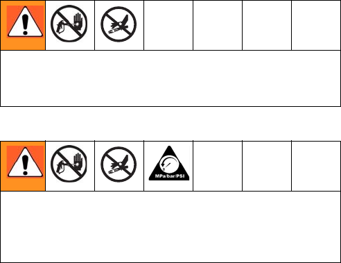
Do not exceed the pressure rating of the lowest rated
component. See the identification label (F
IG. 1 on
page 4).
To reduce the risk of injury, including fluid injection, you
must install a shutoff valve between each fluid supply
line and the fluid manifold assembly. Use the valves to
shut off fluid during maintenance and service.