


Page 9
SKU 92103/104/105 For technical questions, please call 1-800-444-3353
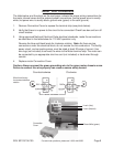
Motor Wire Connections
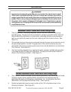
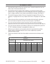
The table below, and the photo on the next page, indicate the proper wiring connections for
the motor internal wires and the external power connections (neutral power wire is usually
white; hot power wire is usually black, ground wire (green) is for earth ground).
1. Remove Connection Cover to expose the terminal strip (see photo below).
2. Verify that there is no power to the circuit to be connected. Check fuse box and turn off
circuit breaker.
3. Using approved National Electrical Code electrical standards, make the connections
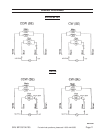
as described in the table below for 115 VAC operation only.
Reverse the blue and black leads for clockwise rotation. Note: As there are tap
connections under the electrical block, do not reverse the line conductors. The facility
power circuit, and connecting wires, must be rated at least 20 amps of current. Use
wire lugs (not included) to connect the wires to the Motor terminal strip. The motor can
be connected by an appropriate size line cord (not included) or hard wired through
conduit.
4. Replace motor Connection Cover.
Caution: Always connect the green grounding wire to the green motor chassis screw.
Failure to connect this wire properly can create a severe safety hazard.
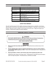
Counterclockwise Clockwise
(1)
Wired from factory
for counterclockwise
rotation
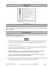
Ground Wire (green)
Line In (Hot)
Line In (Neutral)
Connection
Cover