


TB 9-6625-1996-35
b. Adjustments
(1) Substitute signal generator for function generator.
(2) Connect signal generator RF OUTPUT connector to TI CHANNEL A input.
(3) Connect signal generator EXT REF INPUT connector (rear panel) to TI
FREQ STD OUTPUT 10 MHz connector (rear panel).
(4) Extend front panel display assembly using extender cable 05345-60205.
Disconnect CHAN A P1 caple from A9 J1 CHA (CHAN B P2 cable to A9 J2 CH B for
CHANNEL B) and connect A9 J1 CH A (A9 J2 CH B for CHANNEL B) to oscilloscope
CHANNEL A.
(5) Position TI CHANNEL A and CHANNEL B controls as listed in (a) through
(f) below:
(a) LEVEL control to PRESET.
(b) SLOPE switch to +.
(c) IMPEDANCE switch to 50Ω.
(d) ATTEN switch to X1.
(e) COUPLING switch to DC.
(f) CHECK-COM A-SEP switch to SEP.
(6) Set signal generator frequency to 100 MHz and amplitude to 25 mV.
(7) Position oscilloscope controls as listed in (a) through (f) below:
(a) CH1 VOLTS/DIV switch to .2 V.
(b) SEC/DIV switch to 20 ns.
(c) Pull delayed sweep switch and set to 10 ns.
(d) Set TRIGGER MODE pushbutton to AUTO.
(e) Set TRIGGER SOURCE pushbutton to VERT.
(f) Set TRIGGER COUPLING pushbutton to DC.
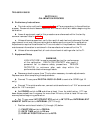
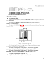
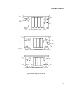
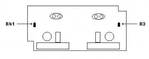
(8) Adjust A3R41 (fig. 2)(A3R3 (fig. 2) for CHANNEL B) for a symmetrical
waveform displayed on oscilloscope (R).
Figure 2. A3 input attenuator (cmponent side).
7
(9) While alternately setting CHANNEL A and CHANNEL B SLOPE switches
to (+) and (-), observe that waveform maintains its symmetrical form.