


INTRODUCTION
DANGER
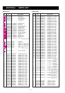
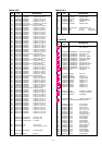
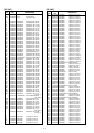
ORDERING PARTS
REPAIR NOTES
This service manual describes the latest service information
for the at the time of publication.
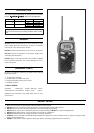
NEVER connect the transceiver to an AC outlet or to a DC
power supply that uses more than 5 V. Such a connection
could cause a fire hazard and/or electric.
DO NOT expose the transceiver to rain, snow or any liquids.
DO NOT reverse the polarities of the power supply when
connecting the transceiver.
DO NOT apply an RF signal of more than 20 dBm (100mW)
to the antenna connector. This could damage the trans-
ceiver's front end.
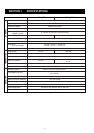
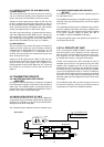
Be sure to include the following four points when ordering
replacement parts:
1. 10-digit order numbers
2. Component part number and name
3. Equipment model name and unit name
4. Quantity required
<SAMPLE ORDER>
0910049951 PCB B-5109B IC-4008A MAIN UNIT 5 pieces
8810009780 Screw PH BO M2x6 ZK IC-4008A Chassis 10 pieces
Addresses are provided on the inside back cover for your
convenience.
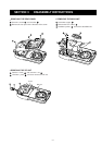
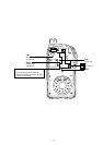
1. Make sure a problem is internal before disassembling the transceiver.
2. DO NOT open the transceiver until the transceiver is disconnected from its power source.
3. DO NOT force any of the variable components. Turn them slowly and smoothly.
4. DO NOT short any circuits or electronic parts. An insulated turning tool MUST be used for all adjustments.
5. DO NOT keep power ON for a long time when the transceiver is defective.
6. DO NOT transmit power into a signal generator or a sweep generator.
7. ALWAYS connect a 30 dB to 40 dB attenuator between the transceiver and a deviation meter or spectrum analyzer when
using such test equipment.
8. READ the instructions of test equipment thoroughly before connecting equipment to the transceiver.
To upgrade quality, all electrical or mechanical parts and
internal circuits are subject to change without notice or oblig-
ation.
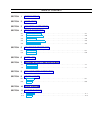
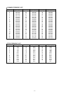
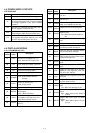
MODEL
VERSION
Italy
C.S.America
SYMBOL
ITA
ITA-1
CSA
CSA-1
BODY COLOR
BLACK
YELLOW
BLACK
YELLOW
IC-4008A
IC-4008MK