


6 - 4
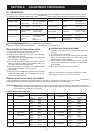
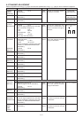
6-2 FREQUENCY ADJUSTMENT
Select an adjustment item using [
↑
] / [
↓
] keys, then set to the specifi ed value using [
←
] / [
→
] keys on the connected PC’s keyboard.
ADJUSTMENT ADJUSTMENT CONDITION UNIT OPERATION VALUE
PLL LOCK
VOLTAGE
(adjustment)
[RX LVA1]
1 Set the preset value of [LV (RX1)], [LV (RX2)] and [LV (TX)] to “204 [4.00V]” on the adjustment software.
2 • Channel
• Receiving
: CH 1 PC
screen
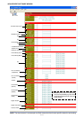
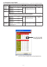
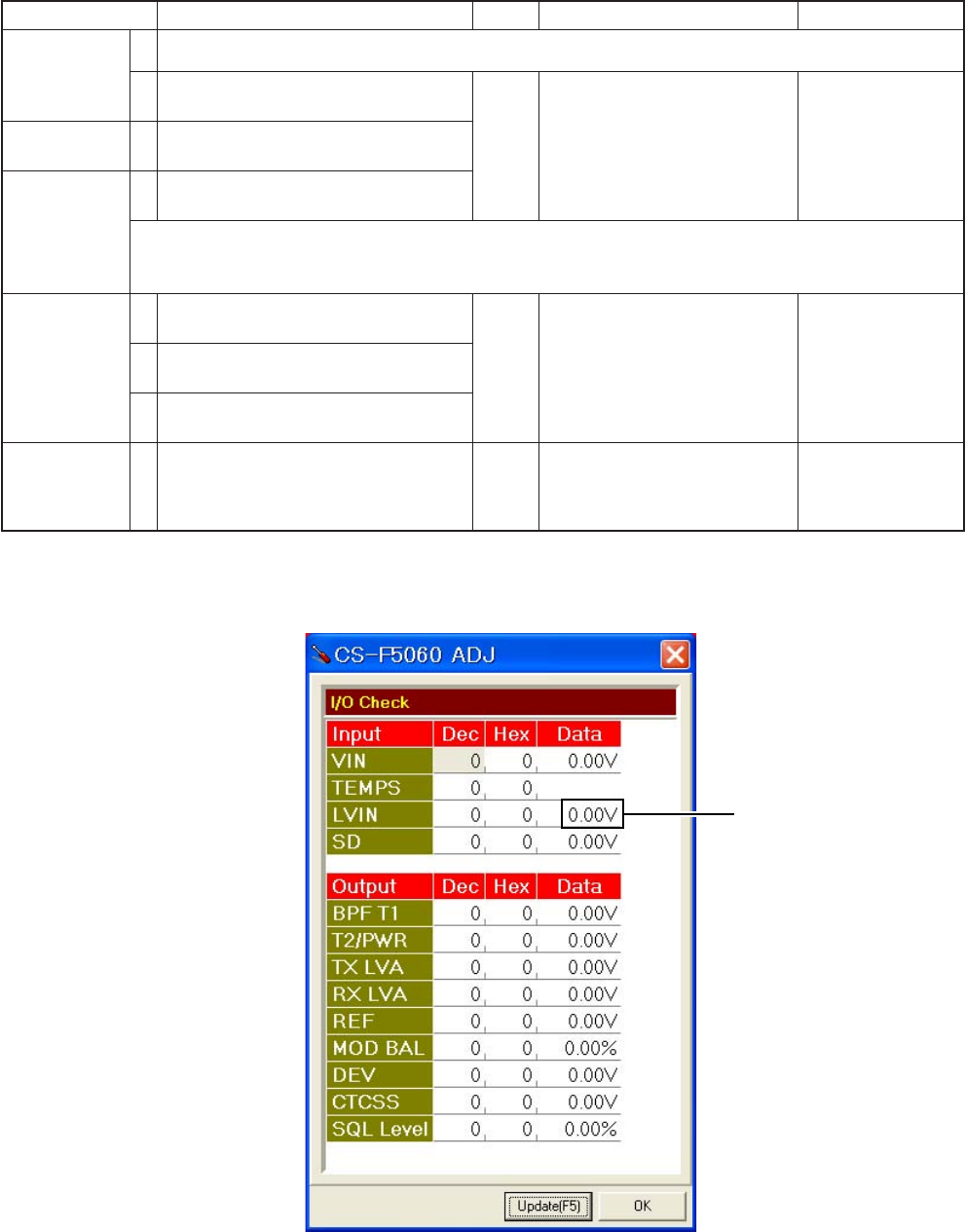
Click [Reload (F5)] button, then
check the “LVIN” item on the
CS-F5060 ADJ’s screen as below.
4.00 V
[RX LVA2] 3 • Channel
• Receiving
: CH 2
[TX LVA] 4 • Channel
• Transmitting
: CH 2
CONVENIENT:
The “
PLL LOCK VOLTAGE”
can be adjusted automatically.
1: Set the Lock voltage preset ([LV RX1], [LV RX2], [LV TX]) to “204 (4.00 V).”
2: Put the cursor on [RX LVA1], [RX LVA2] and [TX LVA], then push the [ENTER] key on the connected PC’s keyboard.
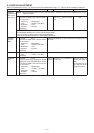
PLL LOCK
VOLTAGE
(verify)
1 • Channel
• Receiving
: CH 3 PC
screen
Click [Reload (F5)] button, then
check the “LVIN” item on the
CS-F5060 ADJ’s screen.
0.8–1.6 V
(Verify)
2 • Channel
• Receiving
: CH 4
3 • Channel
• Transmitting
: CH 3
REFERENCE
FREQUENCY
[REF]
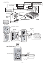
1 • Channel : CH 2 Top
panel
Loosely couple a frequency
counter to the antenna connector.
174.000000 MHz
• Connect an RF power meter to the
antenna connector.
• Transmitting
NOTE: The above screen is an example only.
Each item’s voltage will appear when pushing [Update] button.
PLL LOCK VOLTAGE
will be appeared here