


6 - 5
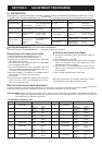
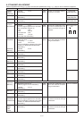
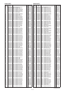
6-3 TRANSMIT ADJUSTMENT
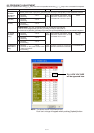
Select an adjustment item using [
↑
] / [
↓
] keys, then set to the specifi ed value using [
←
] / [
→
] keys on the connected PC’s keyboard.
ADJUSTMENT ADJUSTMENT CONDITION UNIT OPERATION VALUE
OUTPUT
POWER
[Power (Hi)]
1 • Channel : CH 5
• Transmitting
Rear
panel
Connect an RF power meter to
the antenna connector.
50 W [USA]
25 W
[EUR], [EXP]
[Power (L2)] 2 • Channel : CH 6
• Transmitting
25 W [USA]
10 W
[EUR], [EXP]
[Power (L1)] 3 • Channel : CH 3
• Transmitting
5.0 W [USA]
2.5 W
[EUR], [EXP]
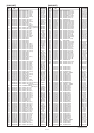
MODULATION
BALANCE
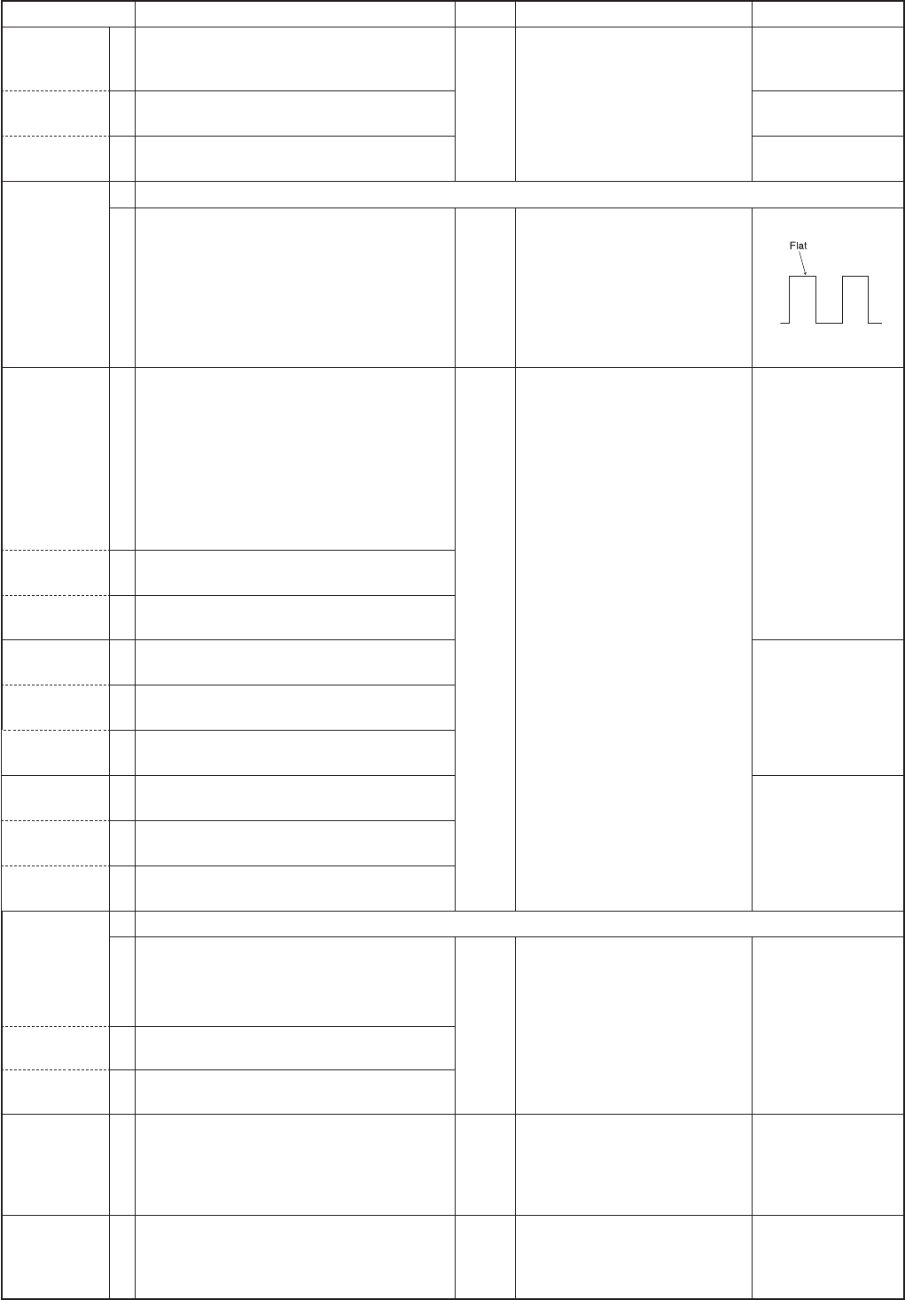
[BAL (Narrow)]
1 Set the preset value of [MOD N] to “100” on the adjustment software.
2 • Channel : CH 7
• No audio signals applied to the JIG cable.
• Set a modulation analyzer as;
HPF : OFF
LPF : 20 kHz
De-emphasis : OFF
Detector : (P–P)/2
• Push [P0] while transmitting.
Rear
panel
Connect the modulation ana-
lyzer with an oscilloscope to the
antenna connector through an
attenuator.
Set to square wave
form
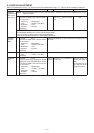
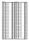
FM
DEVIATION
1
• Connect an audio generator to the JIG
cable and set as;
Frequency : 1.0 kHz
Level : 40 mV rms
• Set the modulation analyzer to the same
condition as “MODULATION BALANCE.”
• Transmitting
Rear
panel
Connect the modulation ana-
lyzer to the antenna connector
through an attenuator.
±2.05 to ±2.15 kHz
(NARROW)
[MOD N C]
• Channel : CH 8
• Transmitting
[MOD N L] 2
• Channel : CH 9
• Transmitting
[MOD N H] 3
• Channel : CH 10
• Transmitting
(WIDE)
[MOD W C]
4
• Channel : CH 4
• Transmitting
±4.05 to ±4.15 kHz
[MOD W L] 5
• Channel : CH 3
• Transmitting
[MOD W H] 6
• Channel : CH 2
• Transmitting
(MIDDLE)*
[MOD W C]
7
• Channel : CH 11
• Transmitting
±3.15 to ±3.25 kHz
[MOD M L] 8
• Channel : CH 12
• Transmitting
[MOD M H] 9
• Channel : CH 13
• Transmitting
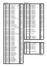
DIGITAL
DAVIATION
[MOD D C]
1
Set the preset value of [Digital Mode] to “7” on the adjustment software.
2
• Attach the UT-119 to J2.
(Refer to page 4-2 for the installation)
Rear
panel
Connect the modulation ana-
lyzer to the antenna connector
through an attenuator.
±1.41 to ±1.45 kHz
• Channel : CH 14
• Transmitting
[MOD D L] 3
• Channel : CH 15
• Transmitting
[MOD D H] 4
• Channel : CH 16
• Transmitting
CTCSS/DTCS
DEVIATION
[CTCS/DTCS]
1
• Channel : CH 17
• No audio signals applied to the JIG cable.
• Set the modulation analyzer to the same
condition as “MODULATION BALANCE.”
• Transmitting
Rear
panel
Connect a modulation analyzer to
the antenna connector through
an attenuator.
±0.68 to
±
0.72 kHz
2TONE,
5TONE,
DTMF
[S.Tone]
1
• Channel : CH 18
• Transmitting
Rear
panel
Connect a modulation analyzer to
the antenna connector through
an attenuator.
±
1.50 kHz
*; [EUR] only.