


PE10X-X-X-A0SPage 6 of 8
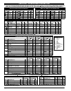
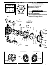
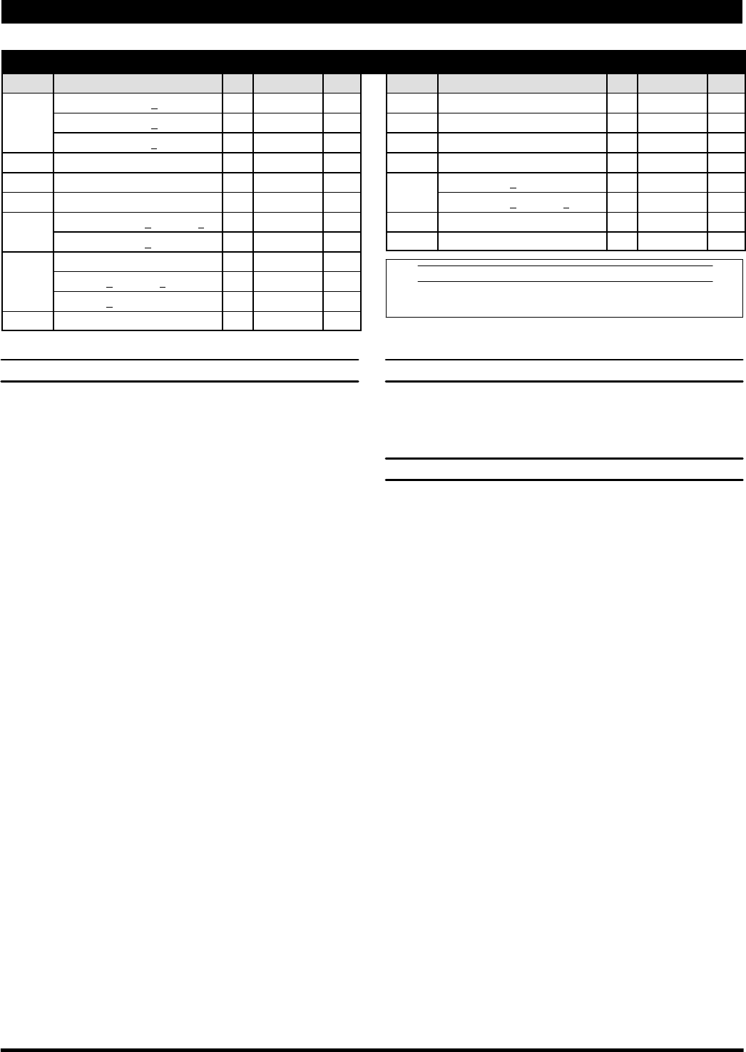
PARTS LIST / PE10X-X-X-A0S AIR SECTION
n Indicates parts included in 637412 Air Section Service Kit shown below and items (70), (144), (175) and (180) shown on page 4.
AIR MOTOR PARTS
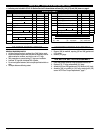
Item Description (size) Qty Part No. [Mtl] Item Description (size) Qty Part No. [Mtl]
101 Center Body (PE10A-X) (1) 95888 [A]
(PE10R-X) (1) 95970 [P]
(PE10S-X) (1) 95901 [SS]
103 Bushing (1) 96000 [D]
121 Plug (2) 96323 [D]
n 132 Gasket (1) 96170 [B]
133 Washer (M6) (PE10A-X and PE10S-X) (3) 95931 [SS]
(PE10R-X) (6) 95931 [SS]
134 Screw (M6x1-6gx25mm) (6) 96340 [SS]
(PE10A-X and PE10S-X) (4) 96340 [SS]
(PE10R-X) (6) 96340 [SS]
160 Air Manifold (1) 96325 [A]
n 166 Gasket (1) 96171 [B]
n 173 “O” Ring (3/32” x 1-3/8” o.d.) (2) Y325-123 [B]
n 176 Diaphragm (check valve) (2) 95845 [SP]
181 Roll Pin (5/32” o.d. x 1/2” long) (4) Y178-52-S [SS]
201 Muffler (PE10R-X) (1) 93139 [P]
(PE10A-X and PE10S-X) (1) 350-568
L n Lubriplate FML-2 Grease (1) 94276
Lubriplate Grease Packets (10) 637308
MATERIAL CODE
[A] = Aluminum [D] = Acetal [SP] = Santoprene
[B] = Nitrile [P] = Polypropylene [SS] = Stainless Steel
K Fluid Section Service Kit Parts, see page 4.
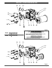
AIR MOTOR SECTION SERVICE
GENERAL REASSEMBLY NOTES:
S Air Motor Section Service is continued from Fluid Section repair.
S Inspect and replace old parts with new parts as necessary. Look for
deep scratches on surfaces, and nicks or cuts in “O” rings.
S Take precautions to prevent cutting “O” rings upon installation.
S Lubricate “O” rings with Lubriplate FML-2 grease.
S Do not over-tighten fasteners, refer to torque specification block on
view.
S Re-torque fasteners following restart.
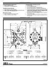
AIR MOTOR SECTION DISASSEMBLY
1. Remove (160) air manifold, exposing (132 and 166) gaskets and
(176) checks.
2. Remove (121) plugs.
AIR MOTOR SECTION REASSEMBLY
1. Clean and lubricate parts not being replaced from service kit.
2. Replace (173) “O” rings and assemble (121) plugs.
3. Assemble (132 and 166) gaskets and (176) checks to (101) body.
4. Assemble (160) air manifold to (101) body, securing with (134)
screws. NOTE: See “Torque Requirements”, page 7.