


OPERATOR’S MANUAL 66523-B
INCLUDING: OPERATION, INSTALLATION & MAINTENANCE.
RELEASED: 1-21-00
REVISED: 8-1-11
(REV. D)
8” AIR MOTOR
6” Stroke
Also covers 66614 service kits.
READ THIS MANUAL CAREFULLY BEFORE INSTALLING,
OPERATING OR SERVICING THIS EQUIPMENT.
It is the responsibility of the employer to place this information in the hands of the operator. Keep for future reference.
INGERSOLL RAND COMPANY LTD
209 NORTH MAIN STREET – BRYAN, OHIO 43506
(800) 495-0276 FAX (800) 892-6276 © 2011 CCN 99834871
www.ingersollrandproducts.com
SERVICE KITS
Use only genuine ARO® replacement parts to assure compat-
ible pressure rating and longest service life.
66614 for general repair of 66523-B air motor.
90350 installation tool is recommended for repair of 66523-B
air motor.
DISASSEMBLY
NOTE: All threads are right hand.
Force the (43) piston assembly up by pushing toward the top
of the air motor (see gure 4).
Remove six (1) screws, releasing the (31) cap and (32) gasket.
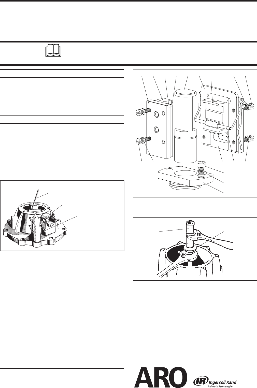
Loosen the eight (45) screws, which hold the (33) valve plate
and pin assembly, (30) valve guide, two (4) valve guides and
the (5) valve plate, until the (30) valve guide and the two (4)
valve guides can be removed by pulling upward (see gures 1
and 2).
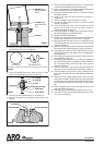
(Use an Allen wrench to push out screws and washers as shown.)
Figure 1
Allen Wrench
46 Washer (8)
45 Screw (8)
(The remaining four
washers and screws are
on the opposite side.)
4. Remove the eight (45) screws and the eight (46) washers from
the 8” air motor by pressure outward with a small Allen wrench
(see gure 1).
5. Using a screwdriver, unhook the (28) insert spring assembly
from the bottom of the (33) valve plate and pin assembly (see
gure 2).
6. Remove the (28) insert spring assembly from the pins in the
top of the (33) valve plate and pin assembly.
7. Pull the (2) valve piston upward until the (7) upper gland has
pulled out of its chamber.
8. Remove the (7) upper gland.
9. Remove the (39) seal, (38) “O” ring and the (13) “O” ring from
the (7) upper gland (see gure 7).
10. Disassemble the (2) valve piston from the (10) piston adapter
(see gure 3).
11. Remove (2) valve piston.
12. Pull the (10) piston adapter upward and grasp the (11) exten-
sion rod below the (10) adapter. Push the (10) piston adapter
down on the (11) extension rod. Remove the (37) washer and
(11) extension rod.
1.
2.
3.
13. Remove the (8) upper washer and the (9) “U” cup packing from
the (10) piston adapter.
14. Remove the six (22) nuts and (23) bolts.
Figure 3
2 10
15. Remove the (35) head assembly and place on the workbench,
with the end that the tube ts in, up.
16. Remove the (16) “O” ring from the (35) head assembly.
17. Remove the four (40) screws, releasing the (41) lower gland.
18. Remove the (12) lower washer and (13 and 42) “O” rings from
the (41) lower gland.
19. Remove (44) tube.
20. Remove the “O” ring from the (44) tube.
21. Pull upward on the (18) air cylinder until the (43) piston as-
sembly separates from the (26) air motor base assembly. If the
(43) piston assembly is not pulled from the (26) air motor base
assembly, remove it after removing the (18) air cylinder.
22. Remove the (16) “O” ring from the (26) air motor base and
bearing assembly.
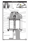
2
4536
30 29
4534
46
28
334645
47
48
7
Figure 2