


Page 2 of 4 66523-B (en)
23. Now remove the (21) retaining ring, (24) guide washer and
(25) “U” cup packing from the (26) air motor base and bearing
assembly.
24. (43) piston assembly is factory assembled and should not be
disassembled.
25. Remove the (17) “O” ring from the (43) piston assembly. CAU-
TION: Do not mar the nish on the piston rod.
26. Disassemble the (43) piston assembly from the (14) screw.
27. Unscrew the (19) valve rod from the (11) extension rod by
holding (19) valve rod with adjustable-type pliers and placing
a wrench on the ats provided at the top of the (11) extension
rod.
ASSEMBLY
NOTE: All threads are right hand. Inspect and replace old parts with
new parts as necessary. Look for deep scratches on metallic sur-
faces. Replace all “O” rings upon reassembly. Lubricate all “O” rings
and “U” cups with Gadus® S2 U1000 grease upon reassembly.
Place (17) “O” ring onto the (43) piston.
Place the (14) screw onto the (19) valve rod. The threaded end
of the screw should be down, away from the threaded end of
the valve rod.
While holding the (19) rod assembly below the threads with
locking type pliers, clean threads with solvent and apply Loc-
tite® 271™ to the threads and attach the (11) extension rod.
Place the (19) valve rod into the hole in the end of the (43)
piston assembly and screw the (14) screw into the (43) piston
assembly.
Thoroughly grease and install the (16) “O” ring in the (26) air
motor base and bearing assembly.
Place the (25) “U” cup packing, (24) guide washer and (21) re-
taining ring in the (26) air motor base and bearing assembly.
1.
2.
3.
4.
5.
6.
Grease and install (13) “O” ring on the (41) lower gland.
Grease the bore in the (35) head assembly and insert (41)
lower gland into the bore of the (35) head assembly with a
twisting motion.
Align the bolt holes in the (41) lower gland and (35) head as-
sembly and secure with four (40) screws.
Push the (43) piston assembly through the (25) “U” cup pack-
ing in the (26) air motor base and bearing assembly, being
careful not to damage the “U” cup packing.
Thoroughly grease the inside of the (18) cylinder.
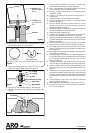
Apply grease to (17) “O” ring, then insert into the bottom of
the (18) cylinder (see gure 5).
Push the (43) piston assembly to the top of the cylinder.
Thoroughly grease and install the (42 and 16) “O” rings in the
(35) head assembly.
Thoroughly grease the two (36) “O” rings and install one on
each end of the (44) tube.
Press the (44) tube into the counterbored hole in the (26) air
motor base and bearing assembly.
Push the (11) extension rod through the (42) “O” ring in the
base of the (35) head assembly.
Align and press the (35) head assembly down until the (18)
cylinder and (44) tube are seated in the head assembly.
Insert the six (23) bolts down through the holes in the anges
of the (35) head assembly and the air motor base and bearing
assembly.
Screw the six (22) nuts on the six (23) bolts. Alternately and
evenly tighten the nuts.
Thoroughly grease and install the (9) “U” cup packing in the
(10) adapter, with the lips of the packing down toward the
thick ange of the (10) piston adapter.
Thoroughly grease and install the (38 and 13) “O” rings in the
(7) upper gland.
7.
8.
9.
10.
11.
12.
13.
14.
15.
16.
17.
18.
19.
20.
21.
22.
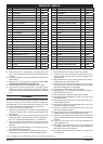
PARTS LIST / 66523-B
Item Description
(size)
(Qty) Part No. Item Description
(size)
(Qty) Part No.
1
Screw
(#10 - 24 x 1/2”)
(6) 95956827
2
Valve Piston (1) 92395
3 Pilot Insert (1) 90487
4 Valve Guide (2) 90481
5 Valve Plate (1) 90480
6 Valve Plate Gasket (1) 90482
7 Upper Gland (1) 91006
8
Washer (1) 91344
9 “U” Cup
(3/16” x 1-3/8” o.d.)
(1) Y186-51
10
Piston Adapter (1) 92393
11
Extension Rod (1) 90080
12
Washer (1) 91345
13 “O” Ring
(1/16” x 1-3/8” o.d.)
(2) Y325-26
14
Screw (1) 92218
16
“O” Ring
(1/8” x 8” o.d.)
(2) Y325-265
17
“O” Ring
(1/4” x 8” o.d.)
(1) Y325-443
18
Air Cylinder (1) 99398
19 Valve Rod (1) 90107-1
21 Retaining Ring
(2.630” o.d.)
(1) Y147-237
22
Nut
(1/2” - 20)
(6) Y11-8-C
23 Bolt
(1/2” - 20 x 10-1/4”)
(6) 94046-1
24
Guide Washer (1) 92216
25 “U” Cup
(1/4” x 1-3/4” o.d.)
(1) Y186-24
26
Air Motor Base Assembly (1) 66525-1
28 Insert Spring Assembly (1) 65807
29 Valve Insert (1) 99202
30
Valve Guide (1) 90488
31
Air Motor Cap (1) 90078
32
Gasket (1) 90083-1
33
Valve Plate and Pin Assembly (1) 65756
34 Valve Plate Gasket (1) 90479
35
Head Assembly (1) 66524-1
36 “O” Ring
(3/32” x 7/8” o.d.)
(2) Y325-115
37 Washer (1) 90105
38
“O” Ring
(0.103” x 1.255” o.d.)
(1) 91207
39 Seal (1) 91007
40 Machine Screw
(#8 - 32 x 3/8”)
(4) Y136-85-S
41 Lower Gland (1) 90114
42 “O” Ring
(1/16” x 7/16” o.d.)
(1) Y325-11
43 Piston Assembly (1) 62109-B
44 Tube (1) 92215
45
Machine Screw
(#8 - 32 x 3/4”)
(8) Y19-89-S
46 Washer (8) 90084
47 Machine Screw
(1/4” - 28 x 3/4”)
(2) Y119-49-C
48 Lock Washer
(1/4”)
(2) Y14-416
49 Ground Lug (1) 93006
Gadus S2 U1000 Grease Pack (2) 94833
Items included in Service Kit 66614
(continued on page 4)
“Smart Parts”, keep these items on hand in addition to the service kits for fast repair and reduction of downtime.
Gadus® is a registered trademark of the Shell Oil Company
ARO® is a registered trademark of Ingersoll-Rand
Loctite® is a registered trademark of Henkel Loctite Corporation
271™ is a trademark of Henkel Loctite Corporation