


Page 4 of 4 66523-B (en)
PN 97999-868
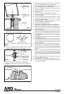
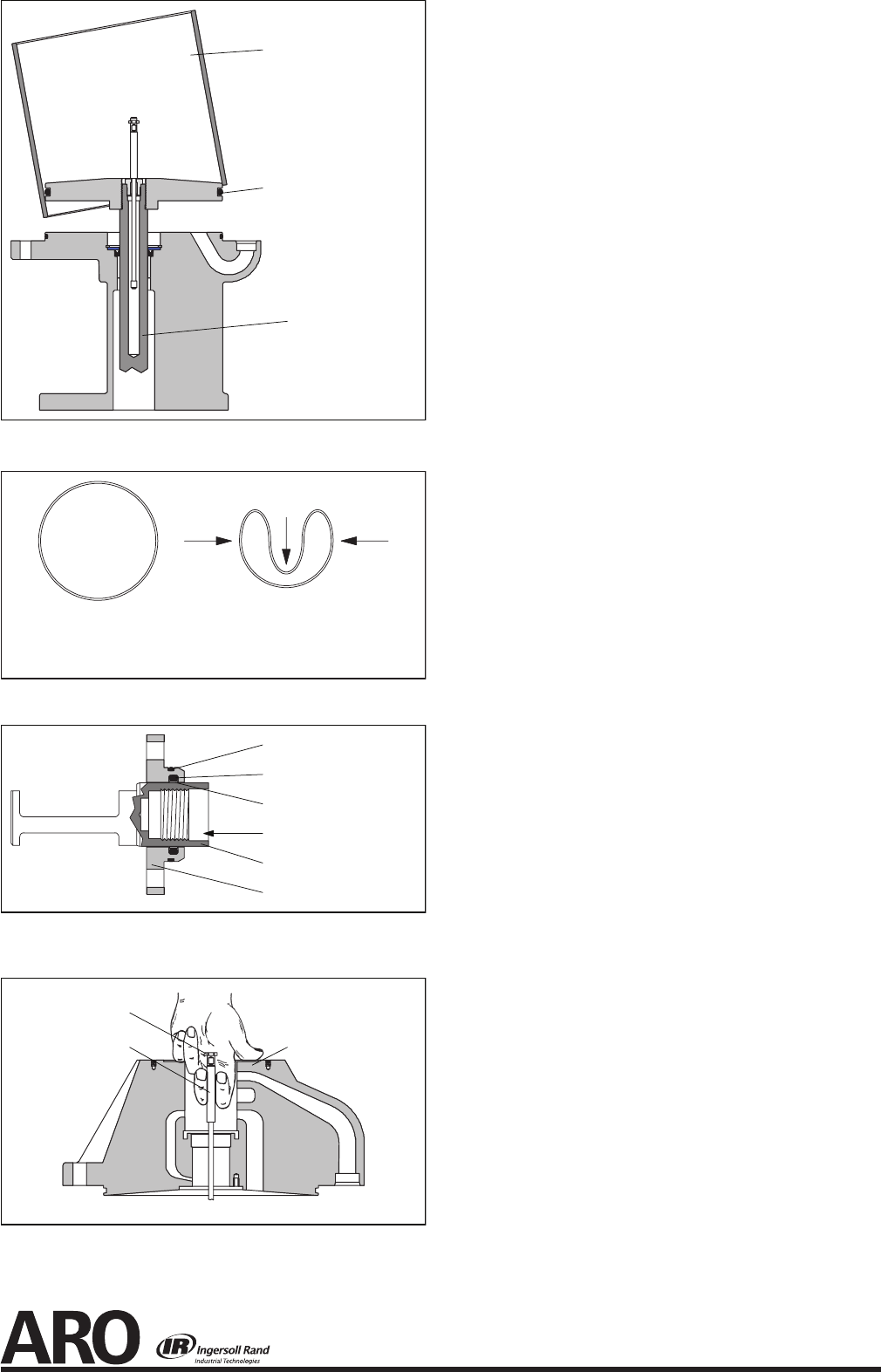
Bend the (39) seal in a heart shape and install in the (7) upper
gland inside the (38) “O” ring (see gure 6).
Figure 6
Seal Free Form Seal Collapsed Form
Push sides in, as shown, then slide into bore and position seal in groove.
24. Grease and carefully push the (2) piston into the (7) upper
gland to size the (39) seal and remove (see gure 7).
Figure 7
13 “O” Ring
38 “O” Ring
39 Seal
Direction for sizing
2 Valve Piston
7 Upper Gland
25. Place the (12) lower washer over the (11) extension rod.
26. Pull the (11) extension rod up and grasp with two ngers, (see
gure 8).
Figure 8
11 Extension Rod
37 Washer
35 Head Assembly
23.
27. Place the 90350 installation tool over the (11) extension rod,
with the turned diameter down and the chamfer up.
28. Fit the turned diameter of the 90350 installation tool into the
bore in the bottom of the (35) head assembly.
29. Place the (10) adapter down over the (11) extension rod, with
the threads upward.
30. Insert the (37) washer into the groove in the top of the (11)
extension rod.
31. Pull the (10) adapter up and around the (37) washer.
32. Place the (8) upper washer over the (11) extension rod and
onto the (10) adapter.
33. Clean the threads with solvent and put Loctite 271 on the
threads of the (2) piston. Screw the (2) piston into the (10)
adapter and tighten (see gure 3).
34. Push the assembled (10) adapter and (2) piston down through
the 90350 installation tool until they bottom.
35. Remove the 90350 installation tool.
36. Install the (7) upper gland over the (2) piston and push down,
being careful to retain the (39) seal in the “O” ring groove.
37. Align the two bolt holes and secure the (7) upper gland to the
(35) head assembly with the two (47) screws and two (48) lock
washers (see gure 2).
38. Insert the (28) spring in the (35) head assembly, with the hooks
down and the nylon roller toward the (2) piston (see gure 2).
39. Thoroughly grease and insert the (3) pilot insert, two (4) valve
guides, (5) valve plate and (6) gasket into the (35) head assem-
bly (see gure 2).
40. Thoroughly grease and insert the (29) valve insert into the (35)
head assembly (see gure 2).
41. Thoroughly grease and insert the (34) valve plate gasket and
the (33) valve plate and pin assembly between the insert and
the (35) head assembly, with the two pins in the (33) valve
plate up (see gure 2).
42. Hook the round coils in the (28) insert spring assembly over
the pins in the (33) valve plate and pin assembly (see gure 2).
43. Hook the bottoms of the (28) insert spring assembly into the
holes on the side of the (33) valve plate and pin assembly (see
gure 2).
44. Insert the (30) valve guide against the face of the (33) valve
plate and pin assembly. The legs of the (30) valve guide should
be down, with the leg having the threaded hole the farthest
from the bottom toward the air inlet in the (35) head assem-
bly.
45. Insert and tighten across corners the eight (45) screws and
eight (46) washers (see gure 1).
46. Thoroughly grease and install the (32) gasket in the (31) cap.
47. Place the (31) cap on the (35) head assembly and secure with
six (1) screws (see gure 4).
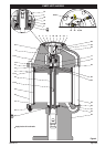
43 Piston
17 “O” Ring (apply
grease around “O”
ring)
18 Cylinder (apply
grease throughout
inside)
Figure 5