


66602X-
X
PAGE 6 OF 8
PUMP
DISASSEMBL
Y AND REASSEMBL
Y
GENERAL PUMP REPAIR NOTES:
S Tools needed to complete disassembly and repair.:
S 7/16" Wrench, 9/16" Wrench,7/16" Socket, 9/16" Socket,
Spanner Wrench, Torque Wrench (measuring inch pounds),
``O"ring Pick.
S Once the pump is disassembled, you have the opportunity to clean
and inspect all parts for wear. Look for deep scratches on metallic
surfaces, and nicks or cuts in ``O"rings. Replace old parts with new
ones as necessary.
S Take precautions to prevent cutting ``O"rings upon installation.
S Lubricate ``O"rings and ``U''cups with Key-lube or equivalent. A
packet of this lubricant is included in each Service Kit.
S Do not over-tighten fasteners, refer to torque specification block
on view.
S Re-torque fasteners following restart.
Service Kits available. From your local distributor.
(Kits also include Keylube grease packet.)
S SERVICE KIT: 637273-XXX contains parts for a complete pump
rebuild.
S SERVICE KIT: 637274-XX contains new check assemblies.
S SERVICE KIT: 637275-XX includes parts to rebuild the air motor
and diaphragms.
S AIR VALVE REPLACEMENT KIT: 637276 includes a complete
factorypre-assembled replacementair valve section.
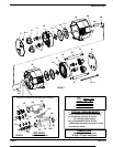
PUMP DISASSEMBLY:
1. Place the pump on a flat workbench. Remove both cover plates
and set them aside.
2. Using a 7/16-inch wrench, loosen the bolts that run through the
pump and remove the six nuts. Pull the bolts through the pump
body and set them aside.
3. The fluid caps and manifolds may fall free at this time. If not, grasp
the fluid caps and separate them from the pump body.
4. The air inlet fluid cap has two small ``O"rings at the air inlet and exĆ
haust ports. Remove these with the ``O"ring pick.
5. The manifold tubes may have pulled free of the pump when the
fluid caps were removed, if not remove both tubes from the pump
body.
6. Remove the ``O"rings from the ends of each manifold tube.
7. If the manifolds did not fall free, separate them from the fluid caps
at this time.
8. To remove the checks, it may be necessary to push a dowel
through the fluid caps.
9. Use the pick to remove any ``O"rings that remain in the manifold or
fluid cap.
10. With the 9/16" socket and 9/16" wrench, loosen and remove either
diaphragm nut. Gently pull the diaphragm away from the pump
body.
NOTE: Models with diaphragms will have back up ``O"rings.
11. Push the connecting rod through the pump body. Wrap the conĆ
necting rod in a shop rag and secure in a soft-jawed vise.
12. Remove the remaining diaphragm nut with a 9/16-inch wrench.
NOTE: Be careful not to mar the connecting rod surface during this
step.
13. Using the 9/16" wrench and the spanner wrench, remove the backĆ
up washer from the diaphragm nut. This will allow you to separate
the diaphragm from the nut.
NOTE: Be careful not to round the diaphragm nut during this step.
14. Pull apart the two air caps. Theconnecting rod bushing will fallfree.
If the air valve block asm. did not fall free, pull it from the air cap at
this time.
15. Use the ``O"ring pick to remove the air cap seal.
16. Use the pick to remove the U-cups and any ``O"rings that may reĆ
main in the air caps.
17. Remove the retaining screws and separate the valve block and miĆ
nor valve block. Pull the piston from the minor valve block. Then
remove all ``O"rings using the pick. Gently push the spool from the
valve block. A dowel may be needed to push out the spool.
NOTE: Be careful not to damage either part during this step.
18. Use the pick to remove all ``O"rings from the spool and the center
gasket from the valve block.
PUMP REBUILD PROCEDURES: (rebuild by service kits)
For the 637273-XXX and 637275-XX Service Kits
AIR VALVE SECTION (Steps 1-6)
1. Install new ``O"rings and U-cup on the spool and piston.
2. Lubricate the spool, piston and internal bores of the valve blocks.
3. Insert the piston into the minor valve block, being careful not to
damage any ``O"rings during this process. Now slide the spool into
the valve block, inserting the small end first.
NOTE: There may be some resistance when installing the piston
and spool, however you should not have to force the parts into
place.
4. Install the shaped gasket into the minor valve block and push the
major valve block into the minor valve block, retain with screws and
torque to 6 in.lbs.
NOTE: Do not lubricate the gasket or valve block surfaces.
5. Insert new, lubricated ``U''cups in each of the air caps. The lips of
the ``U''cups should face towards the diaphragm chambers. Install
the air cap seal.
6. Pre-assemble each of the two diaphragms by first inserting the diĆ
aphragm nut through the new diaphragms, Appy Loctite #242 to
the threads, attach the backup washer, secure with the a 9/16"
wrench and spanner wrench. Using a torque wrench, tighten the
diaphragm nut and washer to 80-inch pounds.
NOTE: Be careful not to round off the diaphragm nut. Backup
``O"rings are included in the Service Kit for models with diaĆ
phragms.
For the 637274-X and 637273-XXX Service Kits:
7. Install new, lubricated ``O"rings onto the four complete check asĆ
semblies that are included with the Service Kit. Also put new
``O"rings on each end of the two manifold tubes.
PUMP REASSEMBLY:
8. First hand tighten the connecting rod to one of the diaphragm asĆ
semblies.
9. Place the air cap on end. Insert the air valve assembly and bushing
in place. (be sure the U-cups are installed). Align logo plates and
push the air caps together.
NOTE: Be sure the bushing, and air valve assembly remain in
place.
10. Lubricate the connecting rod and insert it into the air cap.
NOTE: Models with diaphragms have backup ``O''rings that
are placed in the groove of each air cap.
PTFE
PTFE
PTFE