


PAGE 7 OF 8
66602X-X
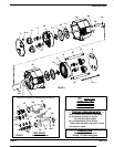
REASSEMBLY (CONT’D)
11. Attach the second diaphragm assembly to the connecting rod,
hand tighten the (pre-assembled) diaphragm nut and washer until
it bottoms out on the connecting rod.
NOTE: Models with Teflon diaphragms have backup ``O"rings that
are placed in the groove of each air cap. Do not over-tighten the
nut.
12. Replace the ``O"rings at the air inlet and exhaust ports of the air inĆ
let fluid cap.
13. Properly align the fluid cap and attach it to the pump body. When in
place, the air inlet should be at the upper right, with the exhaust at
the lower left.
14. Insert a bolt into the bore just below the air inlet and one just above
the exhaust port. Applying a small amount of anti-seize compound
or lubricant to the threads will help prevent the nut from binding.
Properly align the second fluid cap and push it into position.
15. Secure the fluid caps by installing nuts onto each bolts, but do not
tighten fully at this time.
16. Insert the manifold tubes through the pump body,being careful that
the ``O"rings do not fall off during this step.
17. Press two of the check assemblies into the lower inlet ports of the
fluid caps. The checks are keyed and can be assembled only one
way.
NOTE: If the old checks are to be used, clean all parts in an apĆ
propriate solvent.
18. Place manifolds over each check, pushing firmly to secure the
check and the manifold tube.
19. Press the remaining checks into the upper, outlet ports of the fluid
caps. Make sure the smaller seat opening is inserted first.
20. Place manifolds over each check, pushing firmly to secure the
check and the manifold tube.
21. Insert two bolts through each manifold. Secure by attaching a nut
to each bolt. Applying a small amount of anti-seize compound or
lubricant to the threads will help prevent the nut from binding.
22. Tightening sequence for the long bolts:
IMPORTANT ASSEMBLY NOTE: The fastener nuts have ribs
which lock into the material, for best results place a socket wrench
on the nuts so they are held stationary and tighten only the bolts
they are used with.
. Torque all six bolts to 40-inch pounds.
. Cross tighten the bolts in an alternating star shaped
pattern.
. Repeat torque sequence twice.
23. Finish reassembly by pressing both cover plates into place.
TROUBLE SHOOTING
Air Motor stalls
S Check for blown Diaphragm
S Check for damaged ``O"rings on the Spool.
S Check for damaged ``O"rings on the Trip Rod.
S Check valve block gasket for leakage.
Air leaks from Exhaust
S Check for damaged ``O"rings on the Valve Block and Minor Valve
Block, Spool or Trip Rod.
S Check gasket between valve blocks for leakage.
S U-cups on Connecting Rod Bushing are damaged or installed
backwards.
Fluid leaks from Exhaust
S Check for diaphragm damage.
S Check for diaphragm screws not adequately torqued.
Low flow, or pump continues to cycle after shut-off.
S Check for trapped air if the pump is oriented where the inlet check
is above the outlet check. Temporarily increase the flow or re-
prime the pump.
S Check for damaged seats or foreign matter clogging the check asĆ
sembly.
Air leaks from pump (other than exhaust)
S Check for bolts not evenly or adequately torqued.
S Check for ``O"ring missing/damage between the fluid cap and the
air cap on the air inlet side.
External fluid leaks from pump.
S Check for bolts not properly torqued.
S Check for damaged ``O"rings on the Manifold Tube.
S Check for damaged ``O"rings on the Valve Check.
S Check for damaged diaphragm seal.
Pump operates but dispenses little or no fluid
S Check for obstruction in fluid line.
S Check for foreign matter clogging check assemblies.
Note: Install a fluid screen on the material inlet hose if the problem
continues.
S Suction line too small.
S Check for air leakage at the air/fluid inlet pipe plugs. Use
tape or pipe sealant upon assembly.
PTFE