MAINTENANCE AND WARRANTY
SPECIFICATIONS
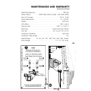
Operating Frequency. . . . . . . . . . . . . . . . . . . . . . . . . . . . . . . . 200 kHz
Power Output . . . . . . . . . 2000 Watts (Peak to Peak) - 250 Watts (RMS)
Area of Coverage . . . . . . . . . . . . . . . . . . . . . . . . . . . . . . 24° at -10 db
Power Requirement . . . . . . . . . . . . . . . . . . . . . . . . . . . . . 10 - 20 VDC
Display. . . . . . . . . . . . . . . . . . . . . . . . . . . . . . . . . . . . . . . . . FSTN LCD
LCD Matrix . . . . . . . . . . . . . . . . . . . . . . . . . . . . . . . . . . . 128 V x 64 H
Viewing Area. . . . . . . . . . . . . . . . . . . . . . . . . . . . . . 2.90" V x 2.35" H
Mounting. . . . . . . . . . . . . . . . . . . . . . . . . . . . Quick Disconnect Mount
Unit Size . . . . . . . . . . . . . . . . . . . . . . . . . . . . . 6
3
/
4
"H x 6
1
/
4
"W x 4
1
/
4
"D
Transducer (Standard) . . . . . . . . . . . . . . . . . . . . . . . . . . . . . . XHS-6-24
Transducer Cable Length . . . . . . . . . . . . . . . . . . . . . . . . . . . . . . . . 20'
Depth Ranges . . . . . . 15', 30', 60', 120', 180', 240', 360', 480', & 600'
Zoom Ranges . . . . . . . . . . . . . . . . . . . . . . . . . . . . 7
1
/
2
', 15', 30', & 60'
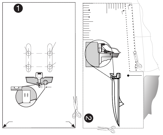
Place on bottom of hull
Align with transom.
DO NOT LET DEADRISE
INTERSECT THIS LINE
PLACE EITHER CORNER
ON DEADRISE ANGLE
TOP
Use 5/32" drill bit
Drill Drill
PLACE EITHER CORNER
ON DEADRISE ANGLE
TOP
Use 5/32" drill bit
DrillDrill
Level
15", 40cm
from prop(s).
PLACE EITHER ARROW
ON DEADRISE ANGLE
TOP
Remove and use for
Transducer Installation
Use ⁵⁄₃₂" drill bit & drill
two holes for hull type
Drill ●
Drill ●
Drill ■
Drill ■
For use with bracket PN 404329-1
Cut and use for Fiberglass Hulls
Fiberglass
Fiberglass Fiberglass
Aluminum
AluminumAluminum
Transducer
Guide
¹⁄₂"
Transducer bottom
Hull
Cut and use for Aluminum Hulls
29


