


27
User Manual
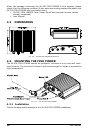
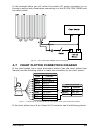
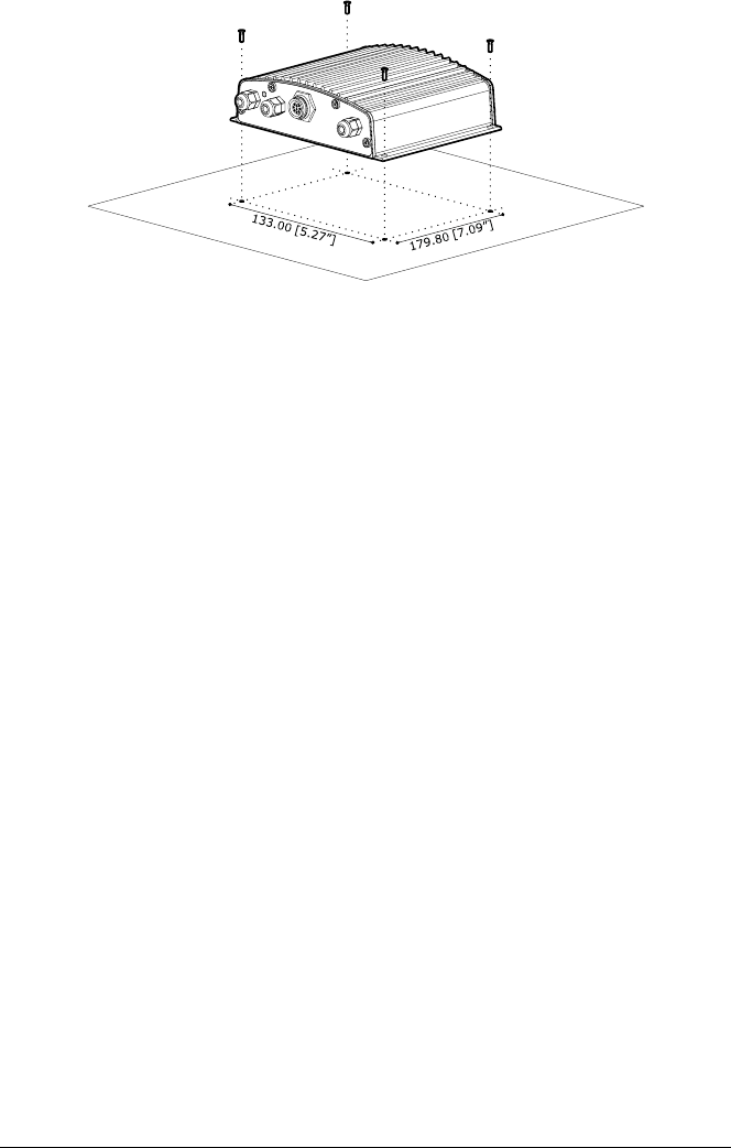
Fig. 4.3.1 - The 50-200 FISH FINDER Installation
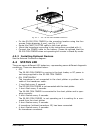
♦ Fix the 50-200 FISH FINDER to the mounting location using the four
screws (holes diameter 4 mm), see Fig. 4.3.2.
♦ Route the CHART PLOTTER cable to the chart plotter.
♦ Mount the transducer according to the instructions provided with it.
♦ Connect the POWER cable to the battery. Please be advised that the
50-200 FISH FINDER when not operating will remain in Stand-By mode.
4.3.2 Installing Optional Devices
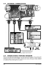
See the External Connection diagram.
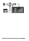
4.4 STATUS LED
There are seven different LED behaviors, representing seven different diagnostic
conditions. These are described below.
♦ OFF
The 50-200 FISH FINDER is running in the boot loader, or DC power is
not being supplied to the 50-200 FISH FINDER.
♦ ON, CONTINUOSLY
The transducer is not connected to the chart plotter or problem with
cable of the transducer cable.
♦ 1 long flash every 2 seconds
The 50-200 FISH FINDER is not connected with the chart plotter.
♦ 1 short flash every 2 seconds
The 50-200 FISH FINDER is connected to the chart plotter and is oper-
ating correctly.
♦ 2 short flashes every 2 seconds
The 50-200 FISH FINDER is not operating as it is waiting for a com-
mand from the chart plotter.
♦ 3 short flashes every 2 seconds
A transducer (without transducer ID) has been connected.
♦ 4 short flashes every 2 seconds:
No transducer connected.