


62
15 CONNECTING PERIPHERAL EQUIPMENT
MCP AND TNC
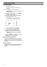
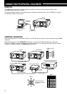
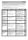
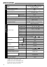
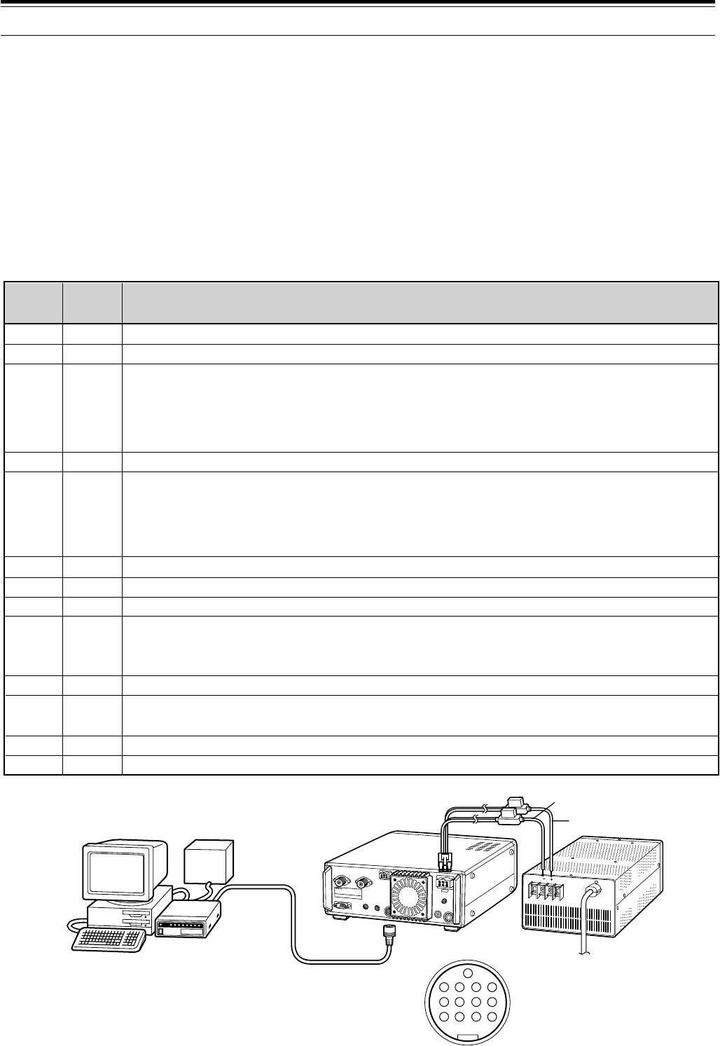
Use the ACC 2 connector to connect the input/output lines from a Terminal Node Controller (TNC) for Packet operation,
a Multimode Communications Processor (MCP) for operation on Packet, PacTOR, AMTOR, G-TOR
TM
, or FAX, or from
a Clover interface. Also use the ACC 2 connector to connect SSTV and phone patch equipment.
• Connect the TNC or MCP to the ACC 2 connector using a cable equipped with a 13-pin DIN plug.
• Connecting the TNC or MCP to a personal computer or dumb terminal requires an RS-232C cable.
Note:
◆
Do not share a single power supply between the transceiver and the TNC or MCP. Keep as wide a separation as possible between the
transceiver and the computer as practical to reduce noise-pickup by the transceiver.
◆
The output voltage of Pin No. 6 (SMET) is not 0 V even when no signal is present. In addition, the output voltage differs between FM
(approx. 2.8 ~ 3.8 V) and other modes (approx. 0.5 ~ 3.8 V). When connecting this pin to peripheral equipment such as a personal computer,
the input impedance of that equipment must be higher than 1 M
Ω
. If you connect to equipment having lower impedance, the S-meter will not
give accurate readings.
TNC/MCP
TS-570
PS-53
13
9101112
5678
1234
TNC/MCP
power
supply
Personal computer
dumb terminal
Black
Red
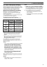
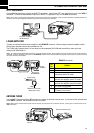
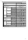
ACC 2 Connector
(Rear panel view)
1
2
3
4
5
6
7
8
9
10
11
12
13
NC
RTK
ANO
GND
PSQ
SMET
NC
GND
PKS
NC
PKD
GND
SS
Pin
Name
Pin No.
Not connected
RTTY key input
AF output from receiver
• Connect to TNC or MCP receive data pin for digital operation.
• AF output level is independent of AF control setting.
• AF output level can be changed via Menu No. 34.
• Output impedance: 4.7 kΩ
Shield for pin 3
Squelch control
• Connect to TNC or MCP squelch control pin for digital operation.
• Prevents the TNC from transmitting while the receiver squelch is open.
• Squelch open: Low impedance
• Squelch closed: High impedance
S-meter output
Not connected
Chassis ground
Transceiver PTT line control
• Connect to TNC or MCP transmit/receive switching pin for digital operation.
• Microphone audio input is muted when the transceiver is switched to the transmit mode.
Not connected
Microphone audio input
• Connect to TNC or MCP transmit data pin for digital operation.
Shield for pin 11
PTT control (in parallel with MIC jack) for connecting a footswitch or other external controller
Function