


2 VHF installation
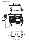
2.1 Location requirements
Please check these before doing any cutting or drilling.
Whichever installation method you choose, ensure that the chosen location:
• Is at least 3’ (1 m) from the antenna
• Allows easy connection to (at least) a 10 Amp fused 13.6 V DC electrical source and
the antenna
• Is at least 1.5’ (45 cm) from the compass to avoid creating magnetic deviation of the
compass during radio operation
• Has a suitable space close by for installing the microphone bulkhead mount
• Provides easy access to the controls on the front panel
• Provides reasonable access to the wiring at the back of the radio
• Provides enough room to x the DSC warning label.
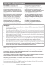
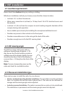
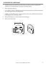
2.2 LCD viewing angle
The VHF has a large LCD screen with an
optimum viewing angle of approx. +/-20
deg. Ensure the chosen location provides a
suitable view of the display. Ideally, the user
should be directly in front of the display or
no more than +/-20 deg from the front of the
display.
Note: If unsure, temporarily power up the
radio and check for a suitable location.
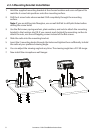
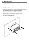
2.3 Choose an installation type
There are two ways to install the radio. You can choose:
• Deckoroverheadmountingbracketinstallation.The reversible mounting gimbal is
xed to a suitable site and the radio is placed into it. The radio can be removed for
storage and the viewing angle can be adjusted.
• Indashorrecessedinstallation.The radio is recessed into a cavity cut into a bulkhead.
The radio xture is permanent and the viewing angle cannot be adjusted.
20˚
20˚
20˚
20˚
Side
Top
Lowrance - Link-8 Installation Instructions 7