


1. INTRODUCTION
The Lowrance X-15A is a
highly
sophisticated recording depth
sounder. Thanks to a micro-com-
puter,
the X-1 5A can do more than
any
other sonar unit in its
price
range plus many
that cost much
more. Thanks to a
waterproof key-
board,
full control of the
system
is
at
your fingertips
to meet the
changing
demands of
varying
bot-
tom
conditions,
water
depth,
and
boat
speed.
You can select the
unit's
sensitivity, suppression
level,
upper
and lower
depth range, pa-
per speed, GRAYLINE,
and
many
more features. The
patented
Lowrance variable
suppression
system
combined with
the new
Discrimination feature not
only
fil-
ters out false
signals
without dis-
torting
the real
ones,
but is
synchronized
with the
GRAYLINE
function to
provide
clear
signals
under all conditions.
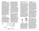
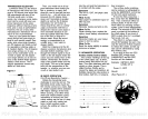
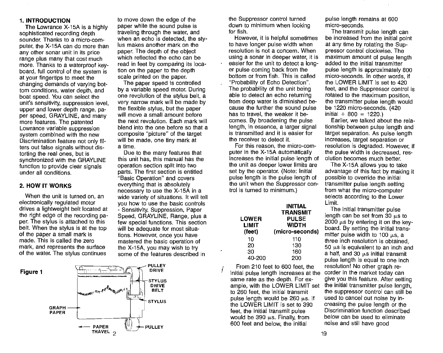
2. HOW IT WORKS
When the unit is turned
on,
an
electronically
regulated
motor
drives a
lightweight
belt located at
the
right edge
of the
recording pa-
per.
The
stylus
is attached to this
belt.
When the
stylus
is at the
top
of the
paper
a
small mark is
made. This is called
the zero
mark,
and
represents
the surface
of the water. The
stylus
continues
Figure
1
to
move down the
edge
of the
paper
while the sound
pulse
is
traveling through
the
water,
and
when an echo is
detected,
the
sty-
lus makes another mark on the
paper.
The
depth
of the
object
which reflected the echo can be
read in feet
by comparing
its loca-
tion on the
paper
to the
depth
scale
printed
on the
paper.
The
paper speed
is controlled
by
a variable
speed
motor.
During
one revolution of the
stylus
belt,
a
very
narrow mark will be made
by
the flexible
stylus,
but the
paper
will move a small amount before
the next revolution. Each mark will
blend into the one before so that a
composite "picture"
of the
target
will
be
made,
one
tiny
mark at
a time.
Due to the
many
features that
this unit
has,
this manual has the
operation
section
split
into two
parts.
The first section is
entitled
"Basic
Operation"
and covers
everything
that is
absolutely
necessary
to use
the X-1SA
in
a
wide
variety
of situations. It will tell
you
how to use the basic controls
-
Sensitivity, Suppression, Paper
Speed,
GRAYLINE,
Range, plus
a
few
special
functions. This section
Will be
adequate
for most situa-
tions.
However,
once
you
have
mastered the basic
operation
of
the
X-15A,
you may.
wish to
try
some of the features described in
PULLEY
DRIVE
sTYLUs
DRIVE
B ELT
STYLUS
the
Suppressor
control turned
down to minimum when
looking
for fish.
However,
it is
helpful
sometimes
to have
longer pulse
width when
resolution is not a concern. When
using
a sonar in
deeper
water,
it is
easier for the unit to detect a
long-
er
pulse coming
back from the
bottom or from fish. This is called
"Probability
of Echo Detection".
The
probability
of the unit
being
able to detect an echo
returning
from
deep
water is diminished be-
cause the further the sound
pulse
has to
travel,
the weaker it be-
comes.
By broadening
the
pulse
length,
in
essence,
a
larger signal
is transmitted and it is easier for
the receiver to detect it.
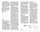
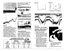
For this
reason,
the micro-com-
puter
in the X-15A
automatically
increases the initial
pulse
length
of
the
unit
as
deeper
lower limits are
set
by
the
operator. (Note:
Initial
pulse length
is the
pulse length
of
the unit when the
Suppressor
con-
trol is turned to
minimum.)
INITIAL
TRANSMIT
PULSE
WIDTH
(micro-seconds)
110
From 210 feet to 600
feet,
the
initial
pulse length
increases at the
same rate as the
depth.
For ex-
ample,
with the LOWER LIMIT set
to 260
feet,
the initial transmit
pulse length
would be 260
pa
If
the LOWER LIMIT is set
to 390
feet,
the initial transmit
pulse
would be 390 is.
Finally,
from
600 feet and
below,
the initial
pulse length
remains at
600
micro-seconds.
The transmit
pulse
length
can
be increased from
the initial
point
at
any
time
by rotating
the
Sup-
pressor
control clockwise. The
maximum amount of
pulse
length
added to the initial transmitter
pulse length
is
approximately
800
micro-seconds. In other
words,
if
the LOWER LIMIT is
set to 420
feet,
and the
Suppressor
control is
rotated to the maximum
position,
the transmitter
pulse length
would
be 1220 micro-seconds.
(420
initial +
800
=
1220.)
Earlier,
we talked about the rela-
tionship
between
pulse length
and
target
separation.
As
pulse length
increases,
target separation
or
resolution is
degraded. However,
if
the
pulse
width is
decreased,
res-
olution
becomes much better.
The X-15A allows
you
to take
advantage
of
this fact
by making
it
possible
to
override the initial
transmitter
pulse
length setting
from what the
micro-computer
selects
according
to the Lower
Limit.
The initial
transmitter
pulse
length
can be set
from 30
s
to
2000
ps by
entering
it on
the
key-
board.
By setting
the
initial trans-
mitter
pulse
width to
100
s,
a
three inch
resolution is
obtained,
50
ps
is
equivalent
to an
inch and
a
half,
and 30
s
initial
transmit
pulse
length
is
equal
to
one inch
resolution! No other
graph
re-
corder in
the market
today
can
give you
this feature. After
setting
the
initial transmitter
pulse length,
the
suppressor
control can still be
used to
cancel out noise
by
in-
creasing
the
pulse length
or the
Discrimination function described
below can be
used to eliminate
noise and
still have
good
LOWER
LIMIT
(feet)
10
20
30
40-200
GRAPH
PAPER
130
160
200
PULLEY
TRAVEL
2 19
PDF compression, OCR, web-optimization with CVISION's PdfCompressor