


2XWOLQHGLPHQVLRQGUDZLQJV
2XWOLQHGLPHQVLRQGUDZLQJV2XWOLQHGLPHQVLRQGUDZLQJV
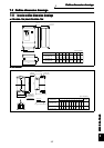
2XWOLQHGLPHQVLRQGUDZLQJV
z
zz
z)59/.Ã....
)59/.Ã....)59/.Ã....
)59/.Ã....
z
zz
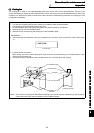
z'&UHDFWRU
'&UHDFWRU'&UHDFWRU
'&UHDFWRU
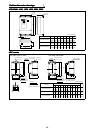
)59/.WR.
)59/..
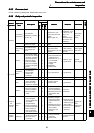
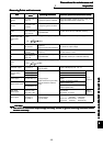
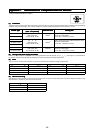
Inverter Type
FR-V540L-110K/132K
FR-V540L-160K
FR-V540L-200K/250K
W
498
(19.61)
680
(26.77)
790
(31.10)
W1
200
(7.87)
300
(11.81)
315
(12.40)
W2
474
(18.66)
656
(25.83)
766
(30.16)
H
1010
(39.76)
1010
(39.76)
1330
(52.36)
H1
984
(38.74)
984
(38.74)
1300
(51.18)
D
380
(14.96)
380
(14.96)
440
(17.32)
D1
185
(7.28)
185
(7.28)
196
(7.72)
C
10
(0.39)
10
(0.39)
12
(0.47)
W
H1
H
3-φC hole
4-φ16 hole
W1 W1
C
D
D1
W2
3.2
(Unit : mm(inch))
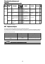
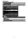
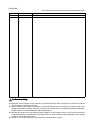
Inverter Type
FR-V540L-110K/132K
FR-V540L-160K
FR-V540L-200K/250K
Outline drawing
X
190
(7.48)
210
(8.27)
220
(8.66)
Y
225
(8.86)
235
(9.25)
250
(9.84)
Z
438
(17.24)
495
(19.49)
495
(19.49)
Z1
305
(12.01)
350
(13.78)
380
(14.96)
B
165
(6.50)
185
(7.28)
195
(7.68)
H
400
(15.75)
450
(17.72)
450
(17.72)
G
38
(1.50)
44
(1.73)
44
(1.73)
S
M8
M10
M10
S1
M8
M8
M8
S2
M8
M8
M8
φ
M12
M16
M16
Mass
(kg(lbs))
36
(79.37)
48
(105.82)
57
(125.66)
P1
P
E
B
X
H ±5
Z ±5
Z
1 ±5
P1
P
2-terminal
(for φ bolt)
Main nameplate
Caution plate
Main nameplate
(Caution plate)
Y ±5
G
2-S2 suspension bolt*
P1
P
E
B
X
H ±5
Z ±5
Z
1 ±5
P1
P
2-terminal
(for φ bolt)
Y ±5
G
2-S2 suspension bolt*
P1 P
Tap diagram
4-installation hole
(for S screw)
Grounding terminal
(for S1 screw)
4-installation hole
(for S screw)
Grounding terminal
(for S1 screw)
*Remove the suspention bolt
after installing the product.
(Unit : mm(inch))
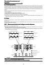
The mark indicates start of coil.