


7URXEOHVKRRWLQJ
7URXEOHVKRRWLQJ7URXEOHVKRRWLQJ
7URXEOHVKRRWLQJ
9)FRQWURO
9)FRQWURO9)FRQWURO
9)FRQWURO
Y
Y
N
N
Y
N
Y
N
Y
N
Y
Y
Y
N
Y
N
N
Y
Y
N
N
N
N
N
N
Y
Y
Y
Y
N
Y
Y
N
N
N
N
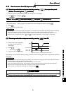
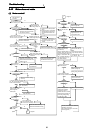
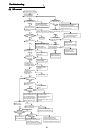
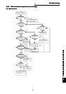
The motor does not rotate.
Is there no alarm output
to the operation panel?
Is the secondary side
wiring (U, V, W) of the
inverter correct without
open cables?
Is the start command
input?
Are the MRS and RES
signals both off?
Is the speed command
input?
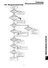
Is an analog
input used?
Apply a voltage to the analog
input terminals (across 2-5).
Also, to calibrate the No. 2
terminal, adjust the bias and
gain of the analog voltage
using Pr. 902 and Pr. 903.
Is the torque boost
setting low?
Set reverse rotation
prevention (Pr. 78)
correctly.
Open the brake.
Set the speed from
the PU.
Turn on the multiple speed
(*RH, RM, RL, REX).
*The terminal functions vary
with input terminal
assignment (Pr. 180 to Pr. 183,
Pr. 187).
Wire the cables correctly.
Make communication setting.
Increase the torque boost.
(Do not increase it too high.
Doing so may cause the motor to
overheat. Increase it to about 10%.)
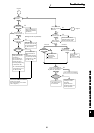
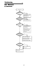
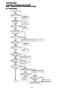
Are the operation panel
LED off and the charge
lamp on?
Are the operation panel
LED on and the charge
lamp off?
Are the earth leakage
breaker and magnetic
contactor on?
Turn on the earth
leakage breaker
and magnetic contactor.
Check for a low voltage,
phase failure, poor
connection or the like
and take corrective action.
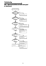
Is the load light?
Is operation performed
without using
communication?
Are the charge lamp
on and the operation
panel LED indication given?
Is the maximum
setting (Pr. 1)
other than 0?
Perform wiring correctly.
PU: Press FWD (REV).
External: Turn on STF (STR).
Also check that both
STF and STR are not on.
Turn off the MRS and
RES signals.
Make the maximum
setting correctly.
Check the alarm definition,
remove the cause of the
alarm, and reset the inverter.
Is reverse rotation
prevention (Pr. 78)
set to enable rotation
in the rotation direction?
When the
electromagnetic brake
is used, is the
electromagnetic
brake open?
Is an external command
used for the speed
command?
Is any cable open?
Are the station number and
so on set correctly?
Lighten the load or increase
the motor and inverter capacities.
The load is excessive,
resulting in a motor lock status.
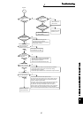
N
Y
Control
Pr.800
Set Pr.800.
2) Connect or DC reactor.
Please contact your
sales representative.
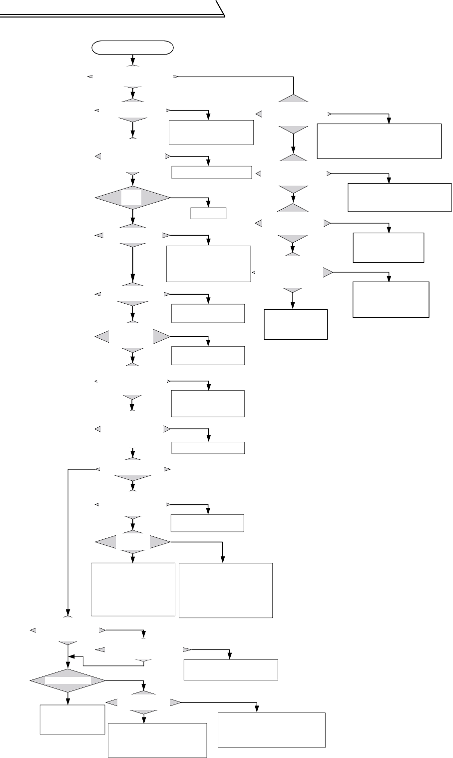
Please contact your
sales representative.
Are the voltages of the
main circuit power
supply voltage terminals
(R, S, T) normal?
1) Contact fault of the operation panel
2) Control power is not supplied.
(Check whether jumpers are connected
across R-R1 and S-S1.)
1) The jumper across P-P1 or
DC reactor is disconnected.