


INSTALLATION/OPERATION MANUAL — REV. #0 (08/19/09) — PAGE 9
CABLE INSTALLATION
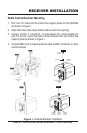
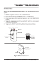
Control Box Removal
Using a 7/16 socket remove the mounting bolts (3) that secure the control box 1.
to the support bracket.
Once the bolts have been removed, fl ip the panel downward to gain access to
2.
the connection points.
Data Cable Connections
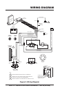
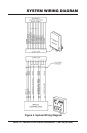
Wire data cable into control box as shown in Figure 2.1.
Crimp a 16-14 (3/16”) terminal ring onto the RED wire labeled BATT+. Connect 2.
this end of the wire to the +12VDC terminal strip, pin 2.
Crimp a #16-14 (3/16”) terminal ring onto the WHITE wire labeled DECREASE.
3.
Connect this end of the wire onto pin 3 on the throttle high low switch.
Crimp a 16-14 (3/16”) terminal ring onto the WHITE wire labeled INCREASE.
4.
Connect this end of the wire to pin 1 of the throttle high low switch.
Crimp a #16-14 (3/16”) terminal ring onto the WHITE wire labeled PIN 9.
5.
Connect this end of the wire to pin 2 on the pumping control switch.
Crimp a #16-14 (5/16”) terminal ring onto the BLACK wire labeled FRAME
6.
GROUND. Connect this end of the wire to engine chassis ground.
Splice the WHITE wire labeled EMERGENCY STOP with the RED or PINK
7.
wire from the engine oil sensor.
Insert connector end of data cable into Miratron receiver.
8.
Remote Control Cable Connections
Connect the remote control cable to the control box as shown in Figure 2 .1.
Splice the WHITE wire labeled REMOTE (data cable) with the BLACK wire 2.
from the yellow remote cable
Crimp a #16-14 (3/16”) terminal ring onto the WHITE wire from the yellow remote
3.
cable. Connect this end of the wire to pin 1 on the pumping control switch.
Re-install control box using the existing mounting hardware.
4.
Insert the yellow remote control cable into the 2-pin receptacle labled REMOTE 5.
OUTLET on the control box.
Reconnect negative battery cable to battery
6. .