


JWN-SERIES RIDE-ON POWER TROWEL • OPERATION MANUAL — REV. #1 (05/12/12) — PAGE 15
GENERAL INFORMATION
JWN SERIES RIDE-ON POWER TROWEL
FAMILIARIZATION
The JWN Series Ride-On Power Trowel is designed for the
floating and finishing of concrete slabs.
Take a walk around your trowel. Take notice of all the
major components like the engine, blades, air cleaner,
fuel system, fuel shut-off valve, ignition switch etc. Check
that there is always oil in the engine, and gear oil in the
gearbox assembly.
Read all the safety instructions carefully. Safety instructions
will be found throughout this manual and on the machine.
Keep all safety information in good, readable condition.
Operators should be well trained on the operation and
maintenance of the trowel.
Look at the operator control levers. Grab the control levers
and move them around a bit. Notice how moving the control
levers causes the gearboxes and frame to move.
Notice the foot pedal which controls the engine speed. Also
take a look at the main drive line of the trowel. Take note
and reference how the belts look, this is the way the belts
should look when adjusted properly.
Before using your trowel, test it on a flat watered down
section of finished concrete. This trial test run will increase
your confidence in using the trowel and at the same time it
will familiarize you with the trowel’s controls and indicators.
In addition you will understand how the trowel will handle
under actual conditions.
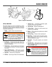
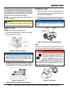
ENGINE
This trowel is equipped with an air cooled 24 HP Honda
gasoline engine. Refer to the engine owner’s manual for
specific instructions regarding engine operation. This
manual is included with the trowel at the time of shipping.
Please contact your nearest Multiquip Dealer for a
replacement should the original manual disappear.
BLADES
The blades of the trowel finish the concrete as they are
swirled around the surface. Blades are classified as
combination (10 or 8 inches wide) and finish (6 inches
wide). This trowel is equipped with four blades per rotor
equally spaced in a radial pattern and attached to a vertical
rotating shaft by means of a spider assembly.
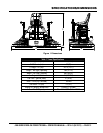
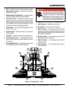
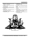
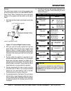
Figure 2 and Figure 3 show the location and functions of the
controls, indicators and general maintenance parts. Each
control may perform more than one function.
GEARBOXES
The JWN Series Ride-On Power Trowel uses two separate
gearbox assemblies that are enclosed in rugged cast
aluminum gear cases.
The gearbox casing has a large oil capacity allowing
optimum lubrication to critical points.
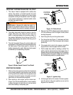
STEERING ASSIST
Dual control levers located in front of the operator's seat
are provided for steering the trowel. The control levers are
linked to two spring loaded cylinders.
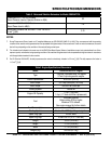
Push the left control lever forward and pull the right control
lever backward and the trowel will rotate clockwise on
approximately a center axis. Pull the left control lever
backward and push the right control lever forward and
the trowel will rotate counterclockwise. See Table 4 for
a complete description on the control levers directional
positioning.
CONSTANT VELOCITY JOINTS (CV-JOINTS)
Constant velocity joints insure the efficient transfer of power
to the drive shaft and maintain the timing of the gearboxes
without any chance of slippage.
TRAINING
For training, please use the “"Training Checklist"” located
in the front of this manual. This checklist is not intended
to be a substitute for proper training but will provide an
outline for an experienced operator to provide training to
a new operator.