


PAGE 34 — JWN-SERIES RIDE-ON POWER TROWEL • OPERATION MANUAL — REV. #1 (05/12/12)
MAINTENANCE
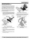
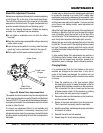
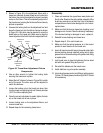
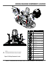
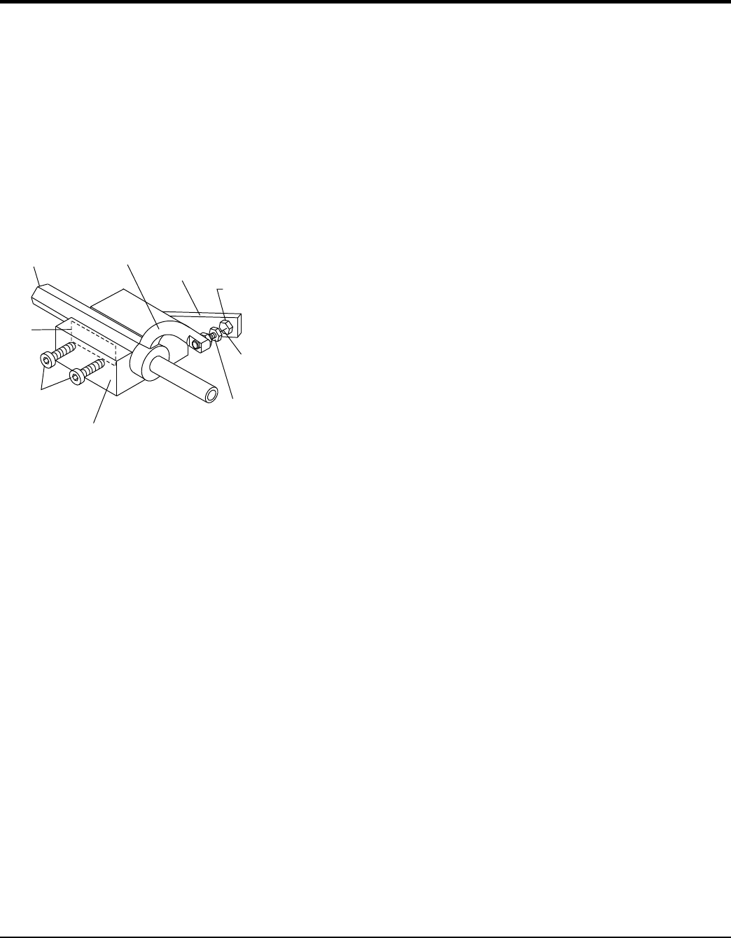
3. Shown in Figure 35 is the adjustment fixture with a
trowel arm inserted. As each trowel arm is locked into
the fixture, the arm bolt is adjusted to where it contacts
a stop on the fixture. This will consistently adjust all of
the trowel arms, keeping the finisher as flat and evenly
pitched as possible.
4. Unscrew the locking bolts on the adjustment tool and
place the trowel arm into the fixture channel as shown
in Figure 35. A thin shim may be required to cover the
blade holes on the trowel arm. Make sure to align the
trowel adjustment bolt with the fixture adjustment bolt.
Figure 35. Trowel Arm Adjustment Fixture
Components
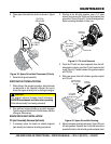
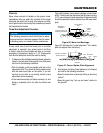
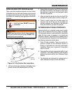
5. Use an allen wrench to tighten the locking bolts
securing the trowel arm in place.
6. Adjust the bolt "distance" shown in Figure 35 to match
one of the arms. The other arms will be adjusted to
match this distance.
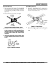
7. Loosen the locking nut on the trowel arm lever, then
turn the trowel arm adjusting bolt until it barely touches
(.010") the fixture adjusting bolt.
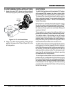
8. Once the correct adjustment is made, tighten the lock
nut on the trowel arm to lock in place.
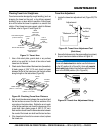
9. Loosen locking nuts on the adjustment fixture, and
remove trowel arm.
10. Repeat steps for the remaining trowel arms
Arm
Trowel Arm
Lever
Fixture
Arm
Adjustment
Bolt
Adjustment
Bolt
Trowel Arm
Adjustment
Fixture
Locking
Bolts
Shim
Distance = .010 in.
Reassembly
1. Clean and examine the upper/lower wear plates and
thrust collar. Examine the entire spider assembly. Wire
brush any concrete or rust build-up. If any of the spider
components are found to be damaged or out of round,
replace them.
2. Make sure that the bronze trowel arm bushing is not
damage or out of round. Clean the bushing if necessary.
If the bronze bushing is damaged or worn, replace it.
3. Reinstall bronze bushing onto trowel arm.
4. Repeat steps 2 -3 for each trowel arm.
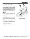
5. Make sure that the spring tensioner is in the correct
position to exert tension on the trowel arm.
6. Insert all trowel arms with levers into spider plate (with
bronze bushing already installed) using care to align
grease hole on bronze bushing with grease hole fitting
on spider plate.
7. Lock trowel arms in place by tightening the hex head
bolt with zerk grease fitting and jam nut.
8. Re-install the blades onto the trowel arms.
9. Install stabilizer ring onto spider assembly.
10. Lubricate all grease points (zerk fittings) with premium
"Lithium 12" based grease, conforming to NLG1 Grade
#2 consistency.