


JWN-SERIES RIDE-ON POWER TROWEL • OPERATION MANUAL — REV. #1 (05/12/12) — PAGE 27
MAINTENANCE
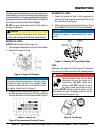
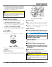
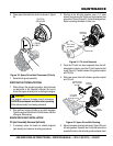
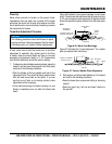
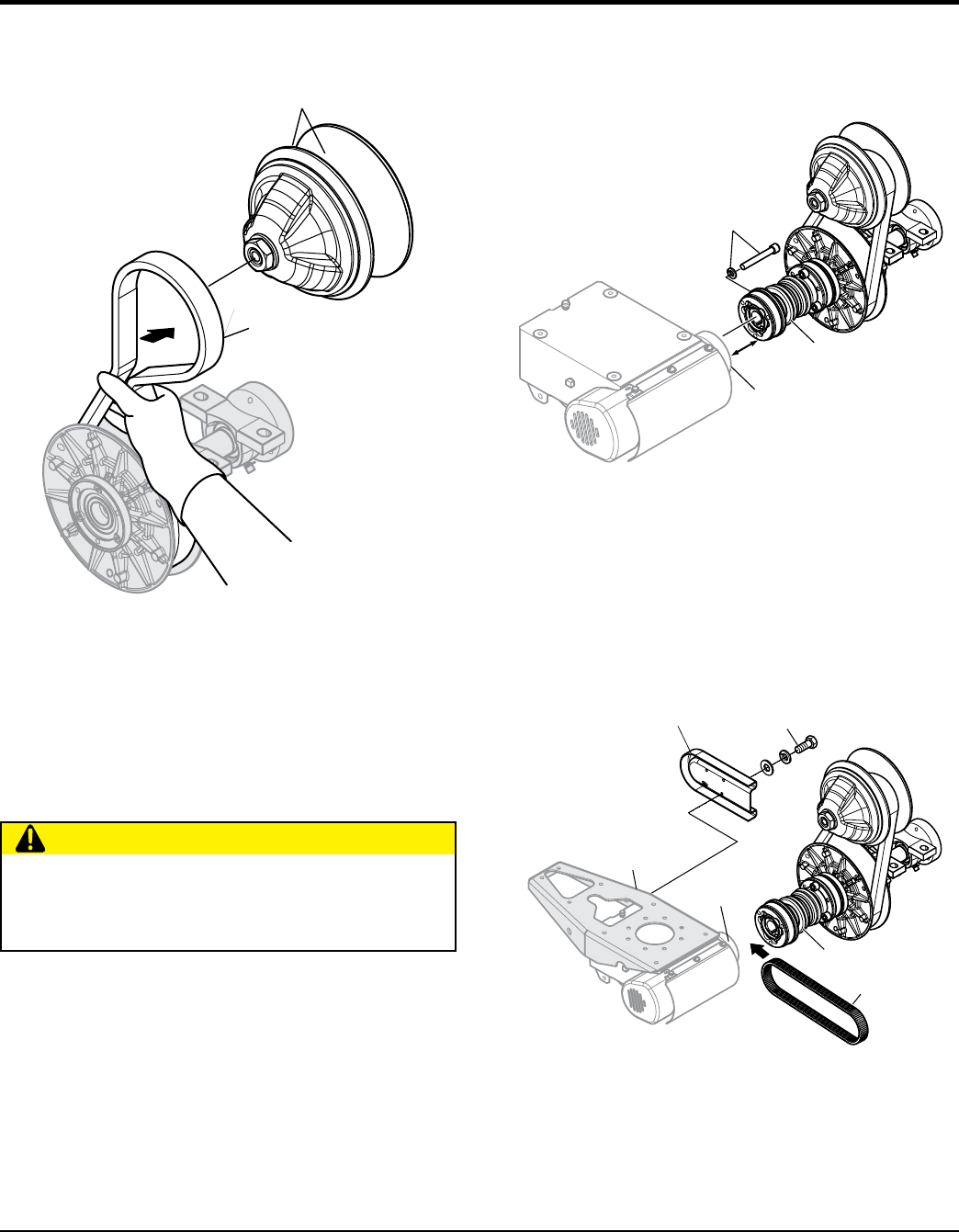
6. Place spare drive belt onto clutch as shown in Figure
20
Figure 20. Spare Drive Belt Placement (Clutch)
7. Reinstall belt guard assembly.
STARTING THE TROWEL/TESTING
1. While sitting in the operator’s position, start the trowel
as referenced in the Operator’s Manual. Be sure to
check the engine oil level prior to starting the engine.
2. Run machine, bringing throttle up so clutch engages.
Cycle the engine from idle to full throttle twice, and shut
off engine. Remove key.
SPARE DRIVE BELT INSTALLATION
CV-joint Assembly Removal (left-side)
1. If necessary, place the trowel on suitable supports
(jack-stands) and observe all safety precautions.
DRIVE
BELT
CLUTCH
GROOVES
CAUTION
The engine’s exhaust contains harmful emissions.
ALWAYS have adequate ventilation when operating.
Direct exhaust away from nearby personnel.
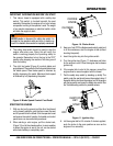
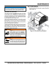
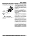
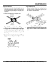
2. Starting at the left-side gearbox, use a 1/4" allen
wrench and remove the 3 bolts and lock washers that
secure the CV-joint (Figure 21) to the left-side gearbox.
Retain mounting hardware for later use.
Figure 21. CV-Joint Removal
3. Once the CV-joint has been separated from the left-
side gearbox coupler, push the CV-joint inward so that
a gap (Figure 21) exists between the gearbox coupler
and CV-joint.
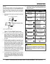
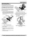
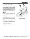
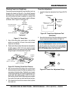
4. Slide new spare drive belt between gearbox coupler
and CV-joint.
Figure 22. Spare Drive Belt Routing
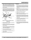
5. Mount new spare drive belt and cover ( Figure 22) onto
left-side gearbox. Reinstall the 2 bolts that secure the
spare belt holder to the left-side gearbox adapter plate.
LEFT-SIDE
GEARBOX
REMOVE
3 PLACES
COUPLER
GAP
CV-JOINT
CV-JOINT
COUPLER
LEFT-SIDE
GEARBOX
ADAPTER PLATE
INSTALL
2 PLACES
SPARE DRIVE
BELT HOLDER
(INSTALL)
SPARE
DRIVE BELT