


6 Pelco Manual C935M (2/97)
NOTE:
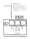
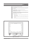
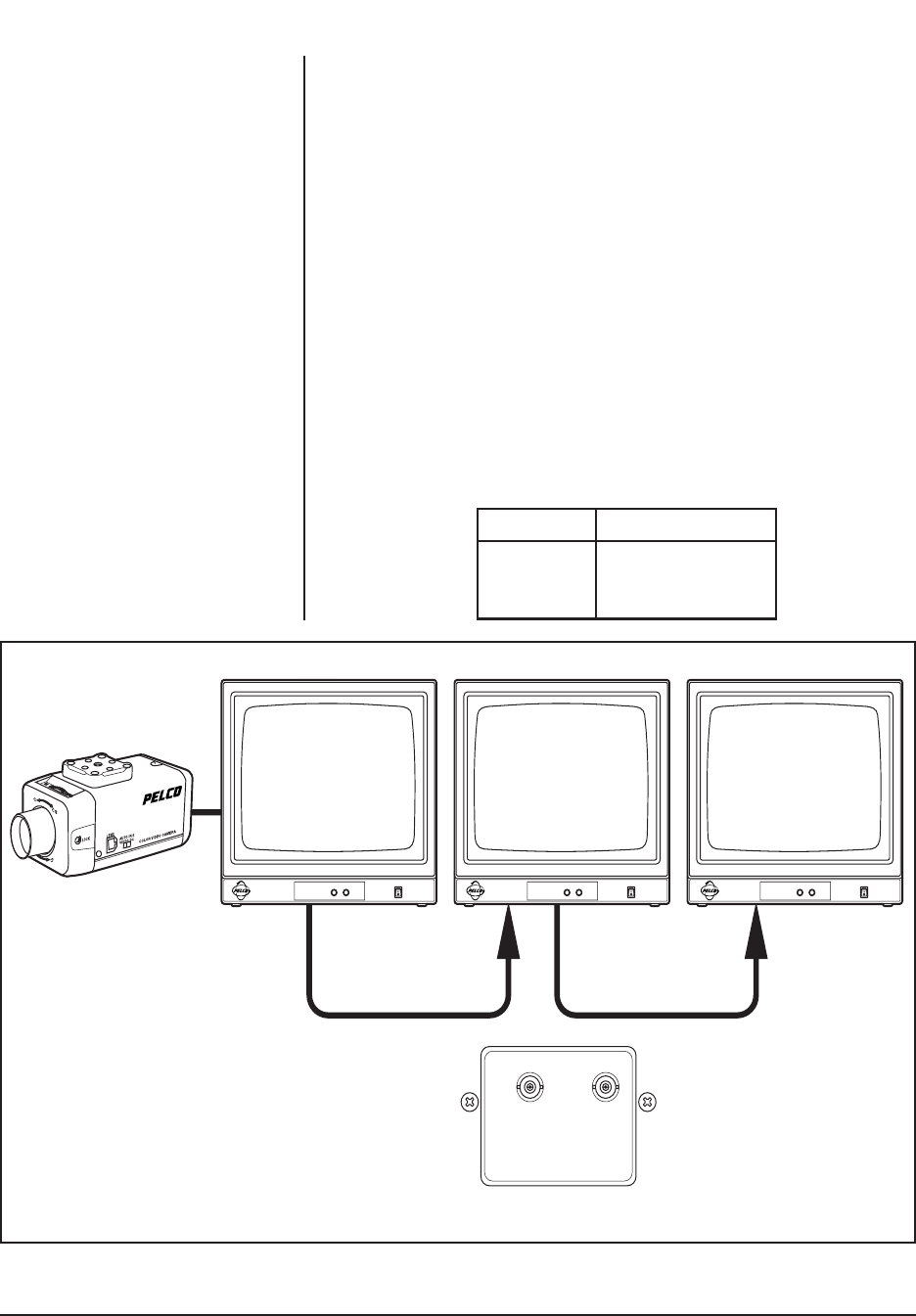
In multiple-monitor instal-
lations, a maximum of three moni-
tors can be connected together.
Figure 2. Multiple-Monitor Installation
FROM OUTPUT
TO INPUT
FROM OUTPUT
TO INPUT
REAR PANEL OF MONITOR
FROM VIDEO
SOURCE TO INPUT
INPUT A OUTPUT A
BRIGHT CONTRASTBRIGHT CONTRAST BRIGHT CONTRAST
3.2.2 Multiple-Monitor Installation
Refer to Figure 2 and Table A for the following instructions.
1. Connect a 75-ohm video cable from the video source, such as a camera, to
the BNC connector labeled INPUT A on the back of the first monitor.
2. Connect a 75-ohm video cable from the OUTPUT A connector on the back of
the first monitor to the INPUT A connector on the second monitor.
3. If you are using a third monitor, connect a 75-ohm video cable from the OUT-
PUT A connector on the back of the second monitor to the INPUT A connec-
tor on the third monitor.
4. For each monitor plug one end of a power cord into the monitor and the other
end into a power outlet.
Table A. Video Coaxial Cable Wiring Distances
Cable Type Maximum Distance
RG59 750 ft (229 m)
RG6 1,000 ft (305 m)
RG11 1,500 ft (457 m)