


5
www.sherwoodscuba.com
Reassembly
15. Install the Exhaust Valves using the same gentle stretching technique used for removal.
16. Install each Exhaust Valve Cover using only your fingers to tighten. Use of tools may damage the
Exhaust Valve Cover.
17. If the demand valve subassembly was cleaned as a unit and not further disassembled install a
new LP Seat (3). Do not attempt to use an old seat as the impression in the old seat may prevent
adequate sealing.
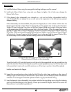
If the subassembly was disassembled, then place the Poppet (4) on a flat surface with the face the
Poppet against the flat surface. Place the Spring (5) over the poppet stem and then place the Lever
Support (6) over the Spring. Press down on the Lever Support taking care to match the square feature
on the poppet stem with the matching square hole in the Lever Support. When the square features are
aligned you will be able to compress the Spring until the Lever Support makes contact with the supporting
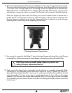
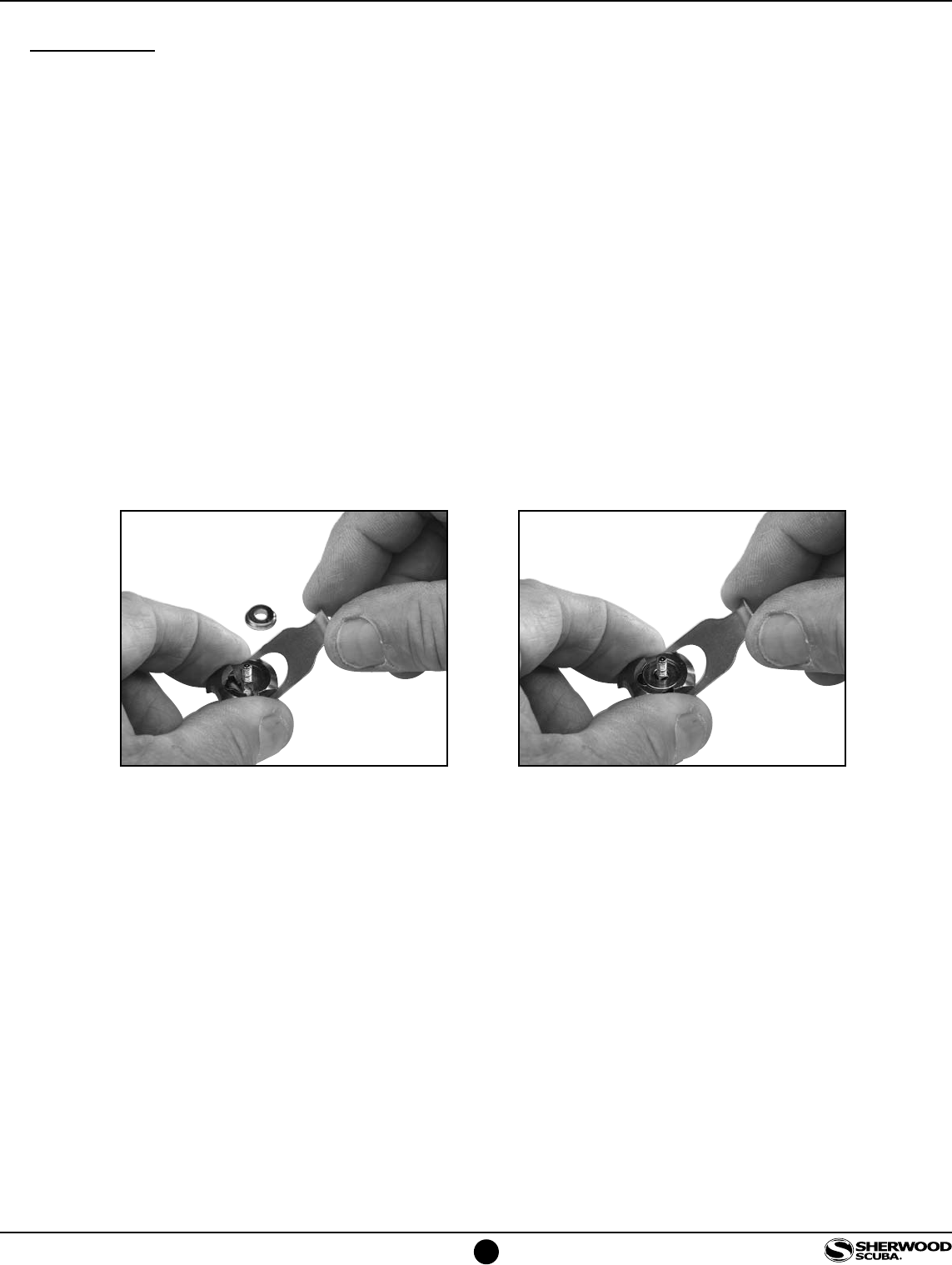
flat surface. While maintaining the applied fore on the Lever Support, insert the Demand Lever as shown
in Illustration 4. Use your fingers to hold the Demand Lever in place and add the stepped Washer (8) to
the subassembly with the smallest diameter making contact with the Demand Lever.
Thread the Lock Nut (9) onto the Poppet just until the end of the poppet shaft starts to protrude from the
end of the Lock Nut. The Lock Nut may be reused for several repeated services, but if it has been used
to the extent that it rotates with very little resistance or will not stay in position it should be replaced.
Install a new Seat into the Poppet.
18. Inspect the crowned seating surface inside the Inlet Fitting for nicks, deep scratches or other signs of
damage. Light corrosion may be removed with a pencil eraser. Do not attempt to polish with abrasive
materials. If it is damaged it should be replaced. Install o-ring (2) onto the Inlet Fitting.
19. Insert the demand valve subassembly into position inside the Housing taking care to align the indexing
notch with the block feature in the Housing. If these parts cannot be aligned, check to be certain the
Demand Lever is not installed upside down.
4) Compress the Spring against a flat surface and add the
Demand Lever and Washer to the subassembly.
1 2