Series 830/840/860 Instruction Manual Chapter 4 Maintenance
IM-83/84/86-H 4-7
Sensor Electrical Test
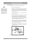
To check the electrical integrity of the sensor windings:
1. Remove the unit from the system.
2. Remove the two 4-40 Phillips head screws located on top of
the electronics enclosure and slide the enclosure up and off.
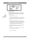
Use a nut driver to remove the two standoffs supporting the
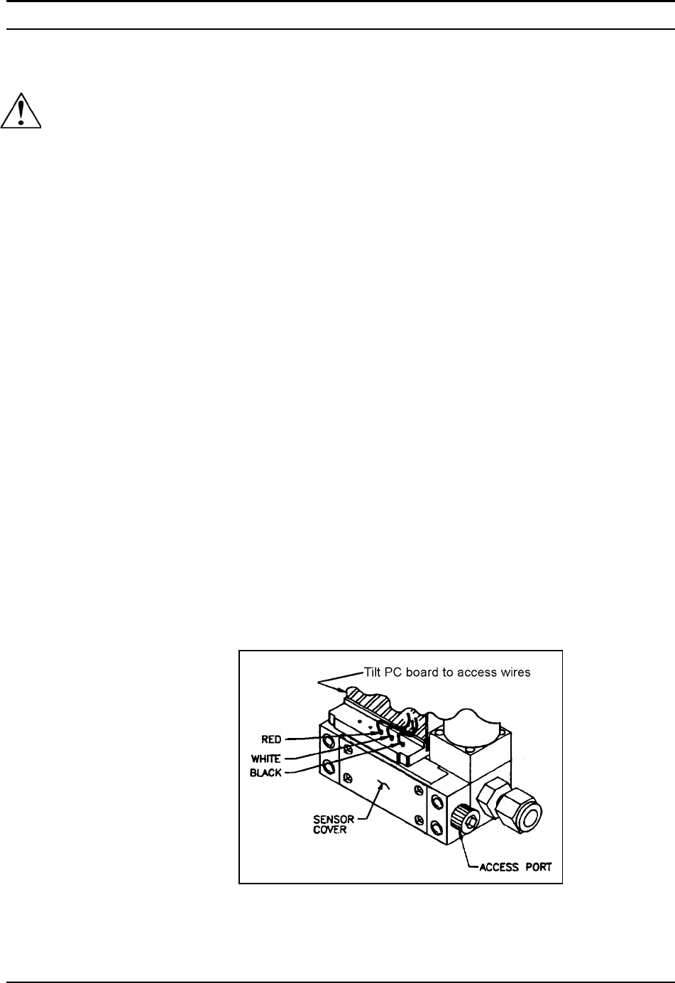
printed circuit boards. Tilt the boards to access the three sensor
wires as shown below.
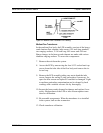
3. Locate the black, red and white wires connecting the sensor to
the main circuit board.
4. Connect one lead of an Ohm meter to the white wire and meas-
ure the resistance between the red and white wires. Next,
measure the resistance between the black and white wires.
These readings should each be approximately 50 Ohms. Low
or zero Ohm readings on either indicates a short circuit. High
or infinite Ohms readings indicate an open circuit.
5. Next, measure the resistance between the case (metal part of
the flow body) and any one of the sensor wires. This reading
should be 2 Megohms or greater. Incorrect readings require
sensor replacement and re-calibration.
6. When the transducer is re-installed in the system, leak test the
connection. Check transducer calibration. See instructions be-
ginning on page 4-13.
Figure 4-5. Sensor Wire Access
Caution!
*Important note: Removal
of the sensor cover and dis-
turbance of sensor insulation
blanket that is inside will alter
the sensors performance,
will necessitate a re-
calibation, and may break
the sensor micro-weldings.


