Series 830/840/860 Instruction Manual Chapter 4 Maintenance
IM-83/84/86-H 4-9
4. The small circuit board may be separated from the main board
to ease removal of the coil. To separate, first remove the plastic
#4 mounting screw located in the center of the main circuit
board and carefully pull the two boards apart. Remove the four
4-40 socket head cap screws at the base of the valve. Separate
the valve from the flow body.
5. There are three O-rings sealing the valve assembly: one be-
tween the base and the flow body, one under the valve seat
(orifice), and one on the top adjusting screw inside the valve.
Inspect the O-rings for damage and replace as necessary. (You
should replace all O-rings whenever the valve is disassembled.)
6. Inspect the valve seat and plug for corrosion or roughness and
replace as necessary.
7. Re-assemble components. Note: the 5/8 inch nut must not be
tightened with more than 10 in-lb of torque.
8. When the controller is re-installed in the system, leak test the
connection.
9. Adjust the valve for proper operation as given in the controller
valve adjustment procedure.
Electromagnetic Valves - High Flow Controllers
The high flow electromagnetic valve is similar in design to the low
flow valve. As with the low flow valve, cleaning can often be ac-
complished by opening the valve using the purge function and
flushing in both directions. Alternatively, the valve may be manu-
ally opened by loosening the 6-32 lock nut on top of the valve and
turning the adjustment screw fully counterclockwise.
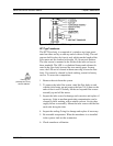
To disassemble the high flow valve:
1. Remove the unit from the system.
2. Remove the two 4-40 Phillips head screws from the top of the
enclosure. Remove the enclosure by sliding it up and off. Re-
move the metal cap on top of the valve by inserting a flat tip
screwdriver between the two parts and lifting upward.
Caution!
When using toxic or cor-
rosive gases, purge the
unit thoroughly with inert
dry gas before discon-
necting from the gas line.


