


PAGE 12 — STR 31V
SVA-SERIES • VIBRATOR MOTOR — PARTS AND OPERATION MANUAL — REV. #1 (06/13/07) — PAGE 12
SVA-SERIES — PREPARATION
1. The vibrator motor, flexible shafting, and heads are shipped
from the factory ready to use. Connect per instruction
bulletins.
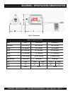
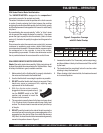
2. Use only the combination of flexible shafting and heads
shown below in Table 3.
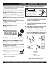
Before using your Vibrator Motor, read and
fully understand all of the safety and
operating instructions not only for the motor,
but also for the flexible shafting and the head
that will be used with the motor.
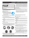
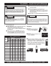
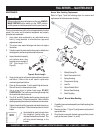
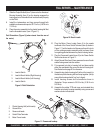
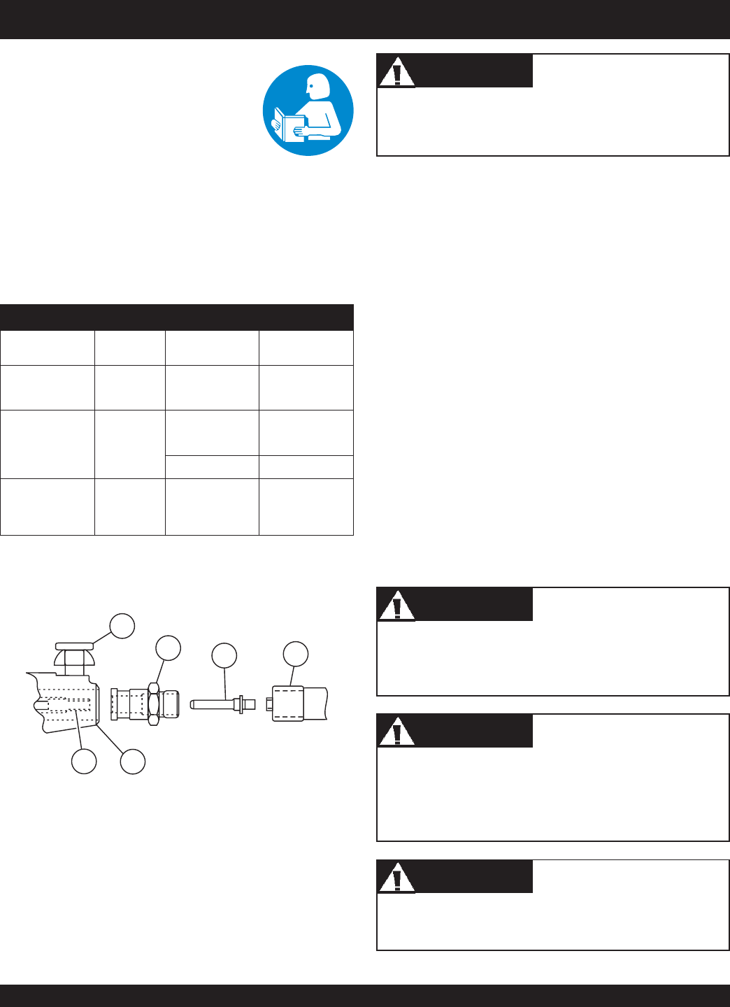
3. To connect the 314V or 382V flexible shafting to the vibrator
motor see illustration (Figure 4).
MAKE CERTAIN the motor is disconnected from the power
source and the switch is in the "OFF" position.
4. Slide the core out of the casing far enough to thread the
spindle (Item 3 Fig. 4) into the core fitting and tighten. A pair
of pliers and a wrench can be used to tighten the connection.
It is important that this connection is tight. If it is not, the
torque of the motor plus the load of the head will jam the two
fittings together making it extremely hard to loosen them for
disassembly.
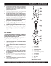
5. Thread the shaft coupling (Item 2 Fig. 4) into the casing
ferrule and tighten.
6. Pull up on the lock pin and slide the shaft assembly into the
front motor bearing housing and release the lock pin. Give
the shaft assembly a twist to make sure that the lock pin is
seated in the lock groove of the shaft coupling.
7. Clean the mating parts threads with Locquic Primer "T".
Allow to dry several minutes before applying a ring of Loctite
No. 271 or equivalent to the middle of the casing threads.
Screw the head tightly to the casing and wait 1 hour before
using. Threads are
left-hand
; turn
counter-clockwise
to
tighten.
If the shaft begins to helix (buckle) excessively during
operation, stop and investigate. This is an indication of an
overload condition.
The vibrator head is cooled by the concrete. Operation of
the vibrator head in air longer than 2 minutes at a time will
cause overheating of the bearings which will result in
premature head failure.
Visually inspect the air intake and exhaust frequently to make
sure the motor has sufficient air for cooling.
WARNINGWARNING
WARNINGWARNING
WARNING
CAUTIONCAUTION
CAUTIONCAUTION
CAUTION
CAUTIONCAUTION
CAUTIONCAUTION
CAUTION
CAUTIONCAUTION
CAUTIONCAUTION
CAUTION
Figure 4. Motor-to-Shaft Connection
seziStfahS.3elbaT
LEDOM TFAHS EZISDAEH
TFAHS.XAM
HTGNEL
1-AVS V413
009
0001
0031
.TF12
2-AVS V283
0041
0071
.TF82
0012 .TF12
3-AVS V283
0041
0071
0012
0062
.TF53
1
2
3
4
6
5
1. Lock Assembly
2. Shaft Coupling Quick Disconnect
3. Spindle Shaft
4. Core Fitting
5. Motor
6. Drive Coupler Quick Disconnect