


SVA-SERIES • VIBRATOR MOTOR — PARTS AND OPERATION MANUAL — REV. #1 (06/13/07) — PAGE 15
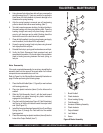
Motor Reassembly
SVA-SERIES — MAINTENANCE
Refer to Figure 8 or the Vibrator Motor Assembly illustration on
page 22 when performing the following steps.
1. Place the Brush Endbell (item 1, Figure 8) on work surface
with bearing pocket up.
2. Place two plastic insulators (items 2) in the holes on the
endbell.
3. Slide the Field Assembly (item 4), with the leads toward
the endbell, into place ensuring the plastic insulators
engage into the field holes.
4. Plug the brush flag leads (see Figure 9, Field Orientation)
into the top of the brush holders toward the output shaft
end. (See Figure 10).
5. Install the Armature/bearings Assembly (item 5) and Wave
Spring (item 3) through the Field and into the endbell
bearing pocket.
6. Place the remaining two plastic insulators (items 6) into the
holes of the Output Endbell (item 7).
If the motor required disassembly for servicing, reinstalling the
assembly back into the case will be much easier if all internal
components are reassembled as a unit first.
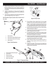
4. Using channel lock style pliers with soft jaws, unscrew the
spring housing (item 3). Heat may need to be applied to
break down the old threadlock to prevent damage to the
threads on the spring housing.
5. After the spring housing is removed, use a 3-jaw bearing
puller to remove the bronze wear bushing, (item 7).
6. To install a new bronze wear bushing, first align the hole in
the new bushing with the spring housing hole. Press the
bushing straight and evenly into place using a block of
wood or soft aluminum and a mallet. Bushing should be
flush with the end of the shaft when fully seated.
7. Clean all old threadlock from the spring housing and apply
new threadlock (Loctite blue 242 or equivalent).
8. Screw the spring housing firmly into place using channel
lock style pliers with soft jaws.
9. Reinstall the lock pin, spring and knob and secure with pin.
10. Verifiy the Quick Disconnect Knob operates freely and
snaps back into position. If the knob stays in the up position
there is binding occurring between the knob, spring, or
lock pin.
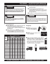
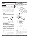
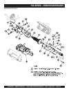
Figure 8. Motor Assembly
1
2
2
3
4
5
6
6
7
8
9
1. Brush Endbell
2. Plastic Insulator
3. Wave Loading Spring
4. Field Assembly
5. Armature & Bearing Assembly
6. Plastic Insulator
7. Output Endbell
8. Lock Washer
9. Screw