


HFM-E-200/HFC-E-202
Page 16 of 30
SYMPTOM: Flow controller oscillates.
CAUSE: Flow controller not adjusted for the dynamics of the flow system.
ACTION: Check upstream and downstream pressures. The gas supply regulator should not have
excessive lockup when flow shuts off. Also ensure that there is not a large drop in pressure between the
regulator and the instrument due to line resistance. Oscillations can also be caused if a large flow
restriction is pneumatically close to the downstream end of the flow controller. The differential
pressure across the unit must be between the values specifications on the original order.
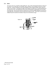
SYMPTOM: Little or no flow, even with a maximum SetPoint value.
CAUSE: Plugged orifice.
ACTION: Verify the presence of a pressure across the instrument. If present, shut off gas supply and
power supply. Remove orifice per Section 4.9. Examine orifice. If plugged, clean or replace as
applicable. Reassemble valve.
SYMPTOM: Flowmeter reads other than 0.00 VDC with no flow, or there is a small flow when Flowmeter
reads 0.00 VDC.
CAUSE: ZERO potentiometer is out of adjustment.
ACTION: Shut off all flow. Adjust ZERO potentiometer until output reads 0.00 VDC.
SYMPTOM: Flowmeter out of calibration and nonlinear.
CAUSE: Leaks in gas inlet or outlet fittings.
ACTION: Check all fittings for leaks by placing soap solution on all fittings between gas supply and final
destination of gas. Check Flowmeter for leaks. Replace “O” rings if required or recalibrate as
necessary.
4.3. ADJUSTMENTS
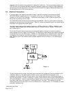
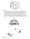
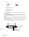
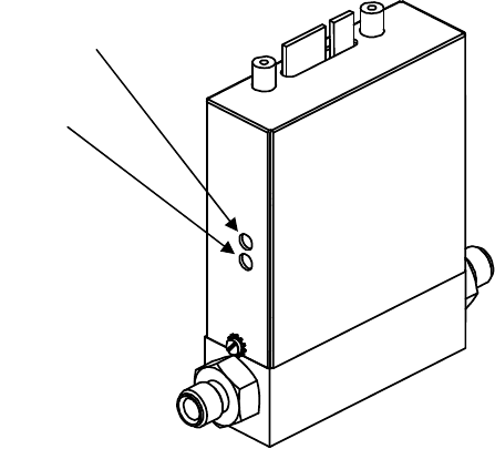
4.3.1. Calibration Procedure: (Figure 4.1)
NOTE: Adjusting the SPAN pot will require the use of a
calibration reference in Step 5.
1. Connect power cable to Edge Connector as specified in Section
2.7. Allow instrument to warm up for 30 minutes. Ensure that for at
least the last 3 minutes there is a controlled flow of gas thought the
instrument, shut off gas flow, wait 2 minutes.
2. Set ZERO (R19) potentiometer for 0.000 VDC output.
3. Turn on gas supply to inlet of instrument. Put Valve Override
switch into CLOSE position. Adjust the orifice underneath controller
to obtain zero flow. Put Valve Override switch into AUTO. Ensure that
full range flow can still be obtained at minimum inlet pressure.
4. Set command to 100%. Wait 2 minutes; adjust SPAN (R29) pot until the flow reference reads full
scale flow (5.000 VDC). NOTE: Perform this step only if a calibrated reference Flowmeter is available.
5. Record Flowmeter and flow reference outputs for flow rates of 20%, 40%, 60%, 80% and 100%.
Zero
S
p
an