


HFM-E-200/HFC-E-202
Page 9 of 30
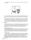
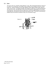
Pin 1 is the case ground. It should be connected to the cable shield if available and to the AC ground at
the power supply.
Pin 3 is the output signal from the flow controller. This output will be 0-5VDC, 5VDC being 100% of rated
or full flow. Pin A is the command input. This should be a 0-5VDC signal and must be free of spikes or
other electrical noise, as these will generate false flow commands that the controller would attempt to
flow.
If a valve override switch is not desired, the unit is ready for use at this time. If the override switch is
desired, connect the center pin of a single pole, three-position switch with the center off position to pin
J. Connect +15VDC to one end of the switch, and -15VDC to the other end. This will result in the valve
being full open when +15VDC is supplied to pin J, off when -15VDC is supplied and auto-control when
there is no connection to pin J (OPEN-AUTO-CLOSE). This setup will be adequate for most purposes, but
there will be a small delay for capacitors to charge between switch operation and control override.
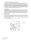
2.6. Operation
The standard instrument output is a 0 - 5 VDC out and the signal is proportional to the flow i.e., 0 volts
= zero flow and 5 volts = 100% of rated flow. The 4 - 20 mA option is also proportional to flow, 4 mA =
zero flow and 20 mA = 100% of rated flow. It is suggested that all connections be checked for leaks after
installation. This can be done by pressurizing the instrument (do not exceed 500 psig unless the
instrument is specifically rated for higher pressures) and applying a diluted soap solution to the
connections.
2.6.1. Operating Conditions
For proper operation, the combination of ambient temperature and gas temperature must be such that
the Flowmeter temperature remains between 10 and 50°C. (Most accurate measurement of flow will be
obtained if the Flowmeter is zeroed at operating temperature as temperature shifts result in some zero
offset.) The HFM-E-201/HFC-E-203 series is intended for use in non-condensing environments only.
Condensate or any other liquids which enter the Flowmeter may destroy its electronic components.
2.6.2. Zero Check
Turn the power supply on if not already energized. Allow for a 1 hour warm-up. Stop all flow through
the instrument and wait 2 minutes. Caution: Do not assume that all metering valves completely shut
off the flow. Even a slight leakage will cause an indication on the meter and an apparent zero shift. For
the standard 0-5 VDC output, adjust the zero potentiometer located on the lower outlet side of the
Flowmeter until the meter indicates zero. For the optional 4-20 mA output, adjust the zero
potentiometer so that the meter indicates slightly more than 4 mA, i.e. 4.03 to 4.05 mA. This slight
positive adjustment ensures that the 4-20 mA current loop transmitter is not in the cut-off region. The
error induced by this adjustment is approximately 0.3% of full scale. This zero should be checked