Manual 111-082010_Nall Mass Flowmeters Page 18 of 23
9.0 Calibration
9.1 CALIBRATION PROCEDURES
The Hastings Mass Flowmeter has been carefully inspected and calibrated at the factory before shipment and
will give long, reliable service. Calibration is stable, and recalibration is seldom necessary under normal
operating conditions; however, to maintain optimum accuracy it is advisable to check calibration on an
annual basis. The unit may be returned to the factory for this purpose, but if that is undesirable, the
following calibration procedure may be of assistance:
1. Connect the power supply to the proper power source (Section 3.4).
2. Turn the power supply “ON” and allow 30 minutes for warm-up.
3. Set the “electrical zero” (Section 3.5).
4. Connect the inlet side of the transducer through a metering valve, to a well-regulated air source and the
outlet to a reliable flow reference such as the Hastings Mini-Flo Calibrator.
5. Check transducer heating voltage as outlined in Section 10.2.1.
6. During normal calibration, a flowmeter is spanned at 80% of full scale to obtain best average linearity.
Example: A 50 SCCM flowmeter with 0-5 VDC output at the binding posts is to be calibrated. If a
reference flow standard is set at a 40 SCCM flow rate, the flowmeter should indicate 80% (.80 X 50 SCCM
= 40 SCCM) of full scale. At this flow rate, the voltage at the binding posts should read 4 VDC (80% X 5
VDC).
CAUTION: Most flow standards are volumetric devices and must be corrected for temperature and
pressure to standard conditions of 0oC and 760 Torr. This correction amounts to several percent at normal
room temperatures and pressures and should not be neglected.
7. If the flowmeter does not agree with the reference flow standard, it is first necessary to correct the output
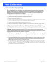
at the binding posts. This is done by making a small adjustment to the “GAIN” potentiometer R-30,
located on the circuit board inside the power supply. This adjustment will also produce a change in the
meter indication.
8. If the meter reading (flow) does not correspond with the binding post’s output (voltage), make a small
adjustment to the “METER” trim potentiometer R-32, located on the circuit board inside the power
supply. This correction has no effect on the output voltage.
9. PC-581A Board Only: Refer to Figure 9.1. Do not change the dipswitch (S2) settings. These settings
are factory pre-set and should only need changing if there is a change in the transducer or the units of
calibration. Switches 1, 2, & 3 change gain and 5, 6, 7, & 8 change the meter range to engineering units.
The number 4 position should remain closed.