


Manual 111-082010_Nall Mass Flowmeters Page 9 of 23
The use of O-ring seal connectors on the transducers with female threads is often more convenient for many
low pressure applications, such as with U-Series transducers.
4.1.5 Checking for Leaks
Check the transducer connections for leaks by pressurizing the line to the operating pressure (not to exceed
250 psig except on high pressure models), and applying a diluted soap solution to the pipe joints. Any gas
escaping from the pipe joints will cause a continuous stream of bubbles.
4.2 FILTERS:
If the flow stream carries particles large enough to block the small passages inside the transducer
(approximately .02” ID) a filter should be installed in the flow line of the inlet side of the transducer.
4.3 CABLES
4.3.1 Description
A standard 5-conductor 20 gauge shielded 8-foot long cable (NF-8-NM) is normally ordered with each
flowmeter and is used for connecting the power and the transducer. Longer cables are available upon special
request.
4.3.2 Cable Length
The cable length can be extended to 25 feet without changing the calibration of the flowmeter by more than
SP+/-1% of the rated full scale flow. Cables longer than 25 feet will cause the indicated flow rate to be lower
than the actual flow rate and recalibration may be required. (See Section 7.0 for calibration procedures.)
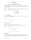
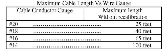
4.3.3 Cable Conductor Size
In the event cable conductors larger than #20 are desired, the connecting cable can be extended to greater
lengths without having to recalibrate the flowmeter. The table below shows the relationship of the conductor
size to the maximum cable length that can be used without changing the calibration by more than 1% of full
scale.
4.4 POWER SUPPLY:
4.4.1 Mounting
One type of housing available for the power supply is a small metal cabinet, 7.75” X 5.75”X 5.75”, which
can sit on a table or desk or can be mounted securely on a bracket. The “NIM” style package is 5.41” X
8.71” X 9.68”, and can be housed in an 8.75” X 19.00” relay rack-panel.
4.4.2 Electrical Connections
Connect the power supply to the transducer with the NF-8-NM connecting cable (Section 4.3) and connect
the AC line cord to a suitable power source (Section 3.4).