


Manual 111-082010_Nall Mass Flowmeters Page 8 of 23
4.0 INSTALLATION INSTRUCTIONS.
4.1 TRANSDUCER
4.1.1 Orientation of the Transducer
The transducer may be mounted in any position, as long as the direction of gas flow through the transducer
is from “IN” to “OUT” as marked on the transducer base. (U-Series transducers should be mounted in a
horizontal position only.)
4.1.2 Mounting the Transducer
There are two ¼-20 threaded holes 3/8” deep in the bottom of the transducer that can be used to secure it to
a mounting bracket, if desired. When the transducer is used in combination with an L or LU Series Laminar
Flow Element (LFE), the LFE should be supported instead of the transducer to prevent undue strain on the
connectors between the transducer and the LFE. Standard pipe support rings or pipe hangers are usually
satisfactory for supporting the LFE.
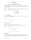
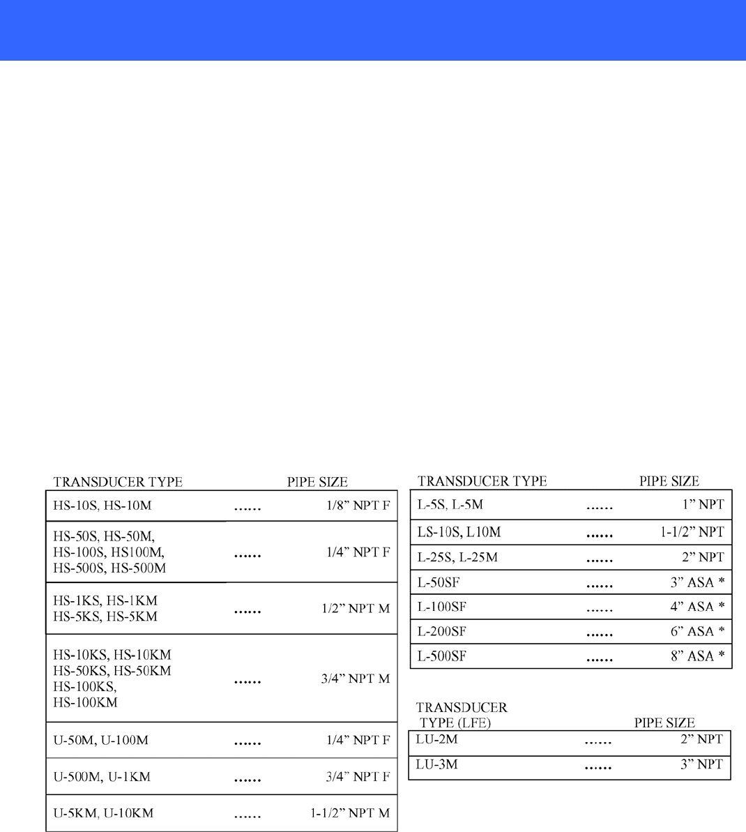
4.1.3 Inlet and Outlet Connections
The table 4.1 describes the inlet and outlet connections for all standard transducers. (If it is necessary to
reduce the pipe size or install an elbow on either side of an L or LU Series Laminar Flow Element, it is
recommended that a straight pipe 12” in length, and of pipe or flange size stated below, be connected
directly to the LFE before connecting a smaller diameter pipe or an elbow.)
4.1.4 Sealing the Threaded Connections
Many users find that Teflon tape is an excellent sealant for most applications, however, any sealant material
compatible with the flow system is acceptable. Caution must be exercised during assembly and disassembly
of the threaded connections to prevent shreds of the Teflon tape, or the sealant from entering the flow line,
where they could block the small passages in the transducer.