


2
INSTALLATION
1. Turn off electrical power to the system at the fuse box
or circuit breaker. Also turn off the main gas supply.
2. If replacing an existing valve, disconnect all plumbing
and electrical connections from the old control.
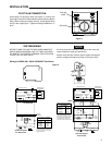
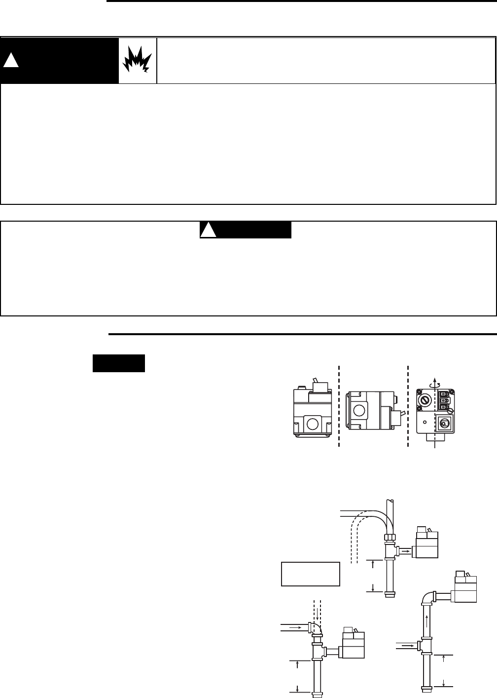
3. The control may be installed in any position except
upside down (see figure 1). The arrow on the bottom
plate indicates the direction of gas flow through the valve.
4. You should use new pipe that is properly chamfered,
reamed, and free of burrs and chips. If you are using
old pipe, be sure it is clean and free of rust, scale, burrs,
chips, and old pipe joint compound.
5. Apply pipe joint compound (pipe dope) or teflon tape that
is approved for all gases, only to the male threads of
the pipe joints. DO NOT apply compound or teflon tape
to the first two threads (see figure 2 for typical piping
connections).
6. If you are using a vise or open-end wrench to hold the
valve while installing piping, do not tighten excessively,
as this may damage the valve.
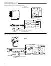
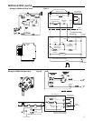
7. See wiring pages 3-6 when making electrical con-
nections. After all gas and electrical connections are
completed, turn gas on and check for gas leaks with
leak detection solution or soap suds. Bubbles forming
indicate a leak. SHUT OFF GAS AND FIX ALL
LEAKS IMMEDIATELY.
NOTE
All piping must comply with local codes, ordinances,
and/or national fuel gas codes.
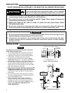
1. Failure to turn off electric or main gas supply to heating system could cause personal injury and/or
property damage by shock, gas suffocation, fire, and/or explosion.
2. Do not use this control on circuits exceeding specified voltage. Higher voltage will damage the
control and may cause shock or fire hazard.
3. NEVER USE FLAME OR ANY KIND OF SPARK TO CHECK FOR GAS LEAKS–COULD CAUSE
FIRE AND/OR EXPLOSION.
4. Do not use a control set for natural gas with LP gas, or a control set for LP gas with natural gas.
Personal injury and/or property damage, gas suffocation, fire, and/or explosion may result.
PRECAUTIONS
CAUTION
!
WARNING
!
If you do not follow these instructions exactly, a fire or explosion
may result causing property damage, personal injury or loss of life.
1. Do not short out terminals on gas valve or primary control to test. Short or incorrect wiring can cause
equipment damage, property damage and/or personal injury.
2. This control is not intended for use in locations where it may come in direct contact with water.
Suitable protection must be provided to shield the control from exposure to water (dripping,
spraying, rain, etc.).
DO NOT BEGIN INSTALLATION UNTIL YOU READ THE FOLLOWING PRECAUTIONS.
Horizontal
Drop
Piped Gas
Supply
Gas Valve
3 in.
minimum
Gas Valve
Riser
Piped Gas
Supply
3 in.
minimum
Drop
Horizontal
Riser
Gas Valve
Tubing Gas
Supply
3 in.
minimum
NOTE:
Always Include
A Drip Leg In Piping
Figure 1. Mounting positions
INLET BOSS
UP OR DOWN
UPRIGHT
LEFT OR RIGHT
Upright, 90° from upright or vertical
NOTE: Control shown may not be identical
to replacement control.
Figure 2. Typical gas valve piping