


14
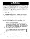
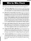
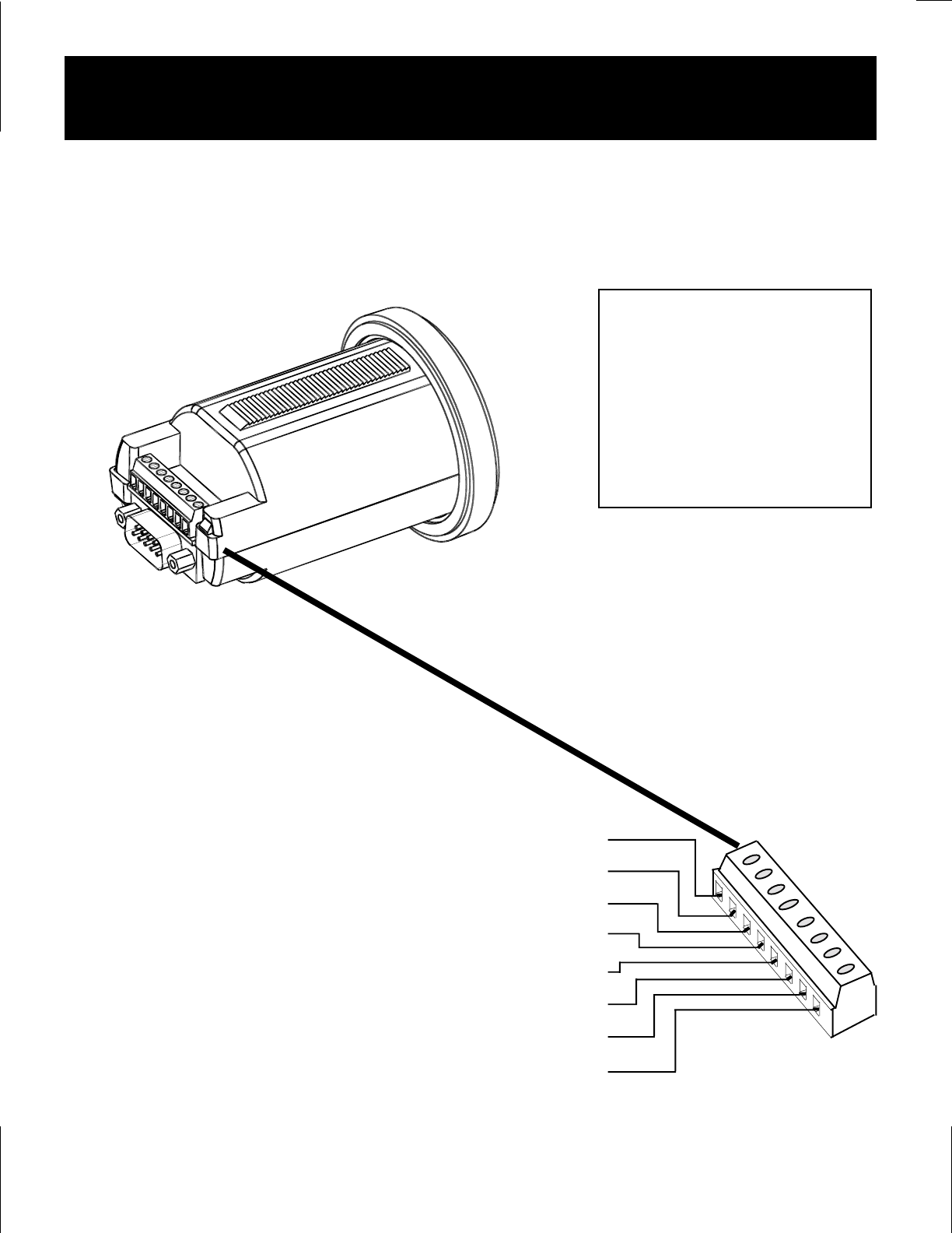
Meter Wiring Detail
Make the necessary wire connections to the Link 10 as
shown in the following diagram:
CAUTION
Use correct sized screwdriver for
terminal screws. Tighten firmly
but do not over-tighten to avoid
damage
Color code shown for
Xantrex 4 twisted pair
cable. P/Ns below:
P/N 84-2014-00 -25'
P/N 84-2015-00 -50'
1) For Voltages above 50 V a Prescaler must be used. See page 44.
DC - Meter Negative (BLACK) [1]
Shunt Sense Lead Load Side (GREEN) [2]
Shunt Sense Lead Battery Side (ORANGE) [3]
Battery Volt Sense (0–50 V DC
1
)(BLUE) [4]
DC + Meter Power (9.5–40 V DC) (RED) [5]
Optional Temperature Sensor Input [6]
Optional Low Battery Alarm [7]
Optional Temperature Sensor Ground [8]
Top Rear View