19
Reading the Bar Graph
Under the LED bar graph are the words
RESETRESET
RESETRESET
RESET,
DADA
DADA
DA
TT
TT
T
AA
AA
A,
LL
LL
L
OCKOCK
OCKOCK
OCK, and
FUNCFUNC
FUNCFUNC
FUNC. These words are ignored during normal operation. They are used
to indicate programming and advanced function modes which are explained
beginning on page 28.
Setting Battery Capacity is Important
The LED bar graph display shows how much of your battery has been con-
sumed. If you do not set your battery capacity correctly, your bar graph will not
give you an accurate indication of battery state-of-charge. The Link 10 also
uses declared capacity to calculate the Time Remaining, the charged current for
Charge Efficiency Factor calculations, and other control functions.
Setting capacity correctly is very important—see page 21
BATTER
Y S
TATE-OF-CHARGE
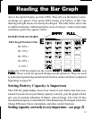
Full (Charged Parameters Met)
80–99%+
60–79%+
40–59%+
20–39%+
0–19%+
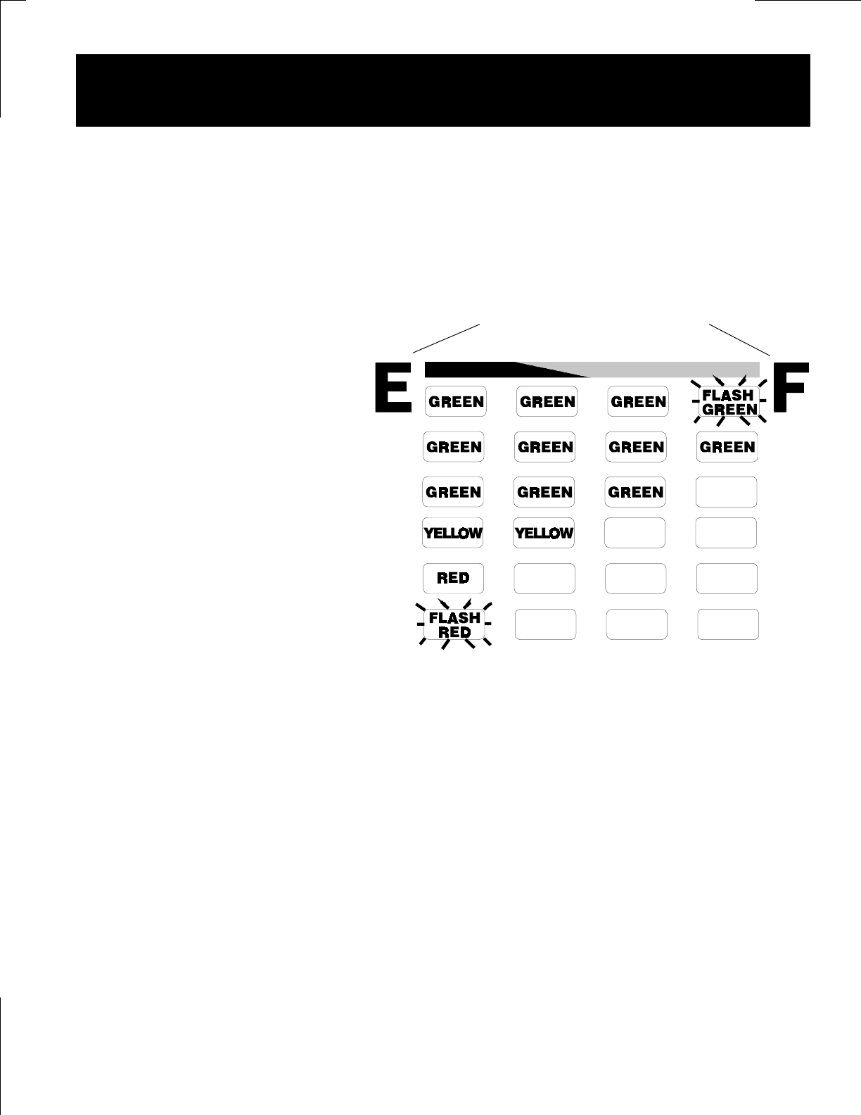
Above the digital display are four LEDs. They tell you the battery's state-
of-charge at a glance. Four green LEDs means your battery is full. One
flashing red light means it is nearly discharged. The table below shows the
six different displays indicating battery state-of-charge. Under certain light
conditions green may appear yellow.
EMPTYEMPTY
EMPTYEMPTY
EMPTY
FULLFULL
FULLFULL
FULL


