3. Service menu
━━━━━━━━━━━━━━━━━━━━━━━━━━━━━━━━━━━━━━━━━━━━━━━
----------------------------------------------------------------------------------------
3 - 8
Screen display
The following screen displays when you select "4;DIO( 1 - 24 )".
Reference
"System"[PF2] -> 2. Controller parameter -> 1. Setting input & output signal -> 7:
Input signal assigning, 6: Output signal assigning Allocated signal displays small
letter.
※ Not allocated signal : O5 , I14
※ Allocated signal : o5 , i14
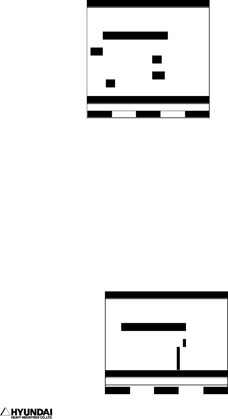
3.1.15 Spot welding Input/Output Monitor
Outline
It displays the status of the welding condition signal, GUN signal, MX signal,
Welding finish Input signal in spot welding..
Screen display
14:39:38 *** M A N U A L *** A:0 S:4
T0 G1
PN:100[*]__ S/F=4/0 Sp:100.00
Robot:H120, 6axes, 1steps
S1 MOVE P,S=100%,A=0,T=1
<< General I/O Signal >>
I1 I2 I3 I4 I5 i6 I7 I8
I9 I10 i11 I12 i13 I14 I15 I16
I17 I18 I19 I20 I21 I22 I23 I24
O1 o2 O3 O4 O5 O6 o7 O8
O9 o10 O11 O12 O13 O14 O15 O16
O17 O18 O19 O20 o21 O22 O23 O24
>
Service System Rel.WAIT Cond Set
14:39:38 *** M A N U A L *** A:0 S:4
T0 G1
PN:100[*]__ S/F=4/0 Sp:100.00
Robot:H120, 6axes, 1steps
S1 MOVE P,S=100%,A=0,T=1
<< Spot Welding I/O >>
WELDg-Cond output = 0 1 2 3 4 5 6 7
Gun output = 1 2
MX output = 1 2
WI in
ut = 1 2
>
Service System Rel.WAIT Cond Set
