9 - 16
9. MELSECNET/H CONNECTION (PLC TO PLC NETWORK)
9.5 Precautions
9.5 Precautions
Network configuration
Use MELSECNET/H (PLC to PLC network) to
configure a network including the GOT.
The following networks including the GOT cannot be
configured.
• MELSECNET/H (Remote I/O network)
Network type setting
• Specify all the network modules on the same network
as the same network type.
(MELSECNET/H Mode and MELSECNET/H
Extended Mode cannot be mixed.)
• When connecting to MELSECNET/H in the QCPU
redundant system, [MELSECNET/H Extended Mode]
cannot be specified as the network type.
Monitoring range
Only PLC CPU of the same networks No. can be
monitored in GOT.
For details, refer to the following manual.
GT Designer3 Version Screen Design Manual
GOT startup in the MELSECNET/H
connection
In the MELSECNET/H connection, the data link is
started approximately 10 seconds after the GOT
startup.
When a network error occurs in the system
alarm
In the MELSECNET/H connection, when a network
error occurs in the system alarm, the system alarm
message cannot be canceled even though the causes
are removed.
To cancel the system alarm display, restart the GOT.
MELSECNET/H network module version
For version restrictions of the MELSECNET/H network
module, refer to the following manual.
Q corresponding MELSECNET/H Network
System Reference Manual (PLC to PLC
network)
Connection in the multiple CPU system
When the GOT is connected to multiple CPU system,
the following time is taken until when the PLC runs.
QCPU (Q mode), motion controller CPU (Q series): 10
seconds or more
MELDAS C70: 18 seconds or more
When the GOT starts before the PLC runs, a system
alarm occurs. Adjust the opening screen time in the
GOT setup so that no system alarm occurs.
GT Designer3 Version Screen Design Manual
Connection to QSCPU
The GOT can only read device data and sequence
programs by the ladder monitor function in the QSCPU.
The GOT cannot write any data to the QSCPU.
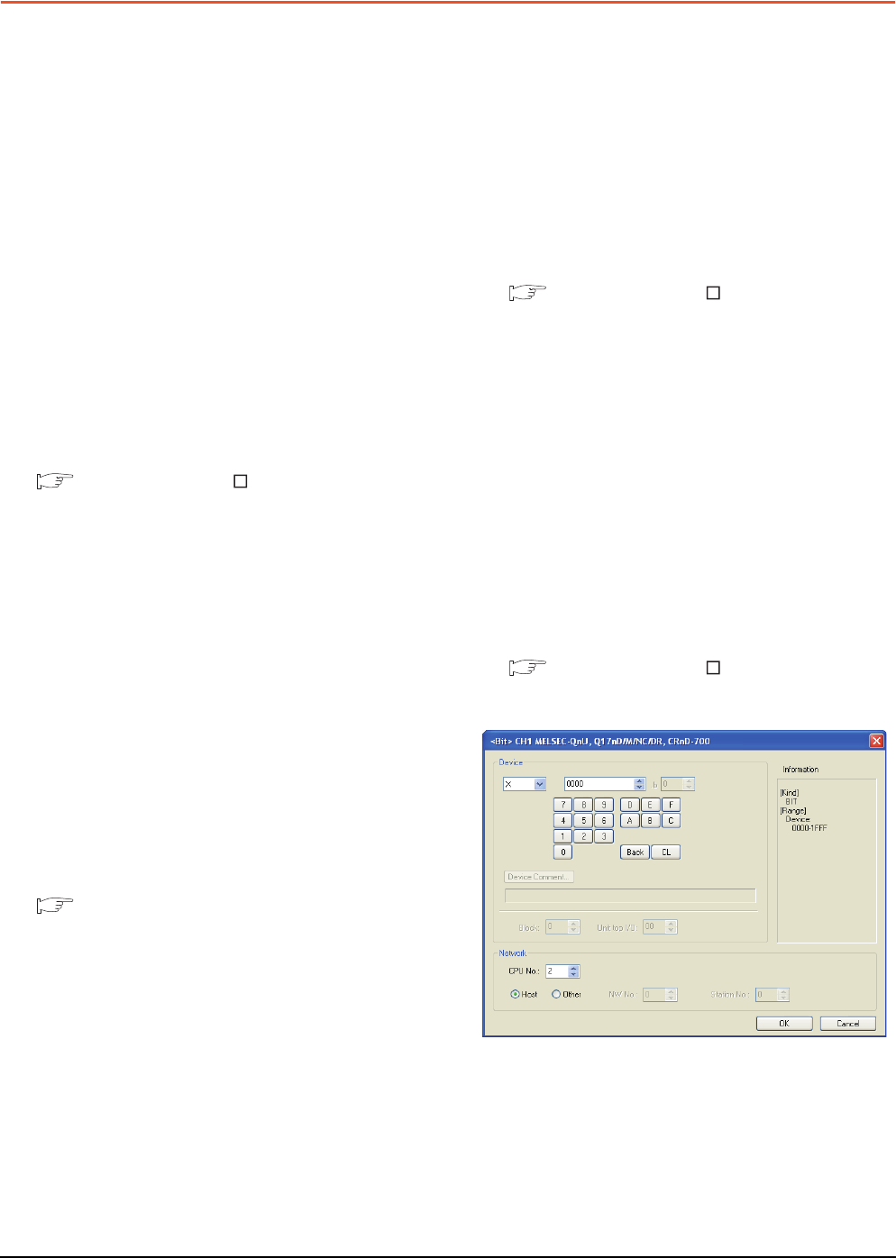
Connection to Q170MCPU
Set [CPU No.] to "2" in the device setting to monitor the
device of the Motion CPU area (CPU No.2).
When the CPU No. is set to "0" or "1", the device on the
PLC CPU area (CPU No.1) is monitored.
When the CPU No. is set to the number other than "0"
to "2", a communication error occurs and the monitoring
cannot be executed.
For setting the CPU No., refer to the following manual.
GT Designer3 Version Screen Design Manual
Example) Setting dialog box of the bit device
