FAILURE MECHANISMS
The strength of the stitches must also be sufficient to ensure that the through-
thickness tension cannot rupture them. This enforces a second condition on the stitch
density [4.28]:
(4.5)
where
σ
s
is the strength of a stitching tow and it has been assumed that the fiber volume
fraction within a stitch = 0.67. Which of Eqs. (4.4) and (4.5) is the more stringent
condition depends on the relative curvature of the panel and the various material parameters
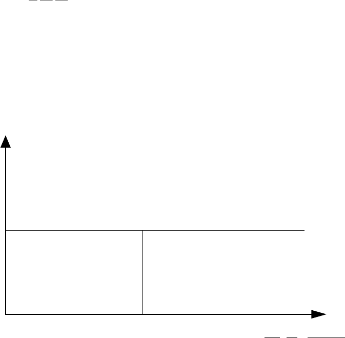
involved. The possible failure modes for a curved part are mapped in Fig. 4-9.
I.
h/r
m
< 0.2 = kink failure under in-plane compression
h/r
m
> 0.2 = ply rupture under in-plane tension
II. rupture of stitching
fibers
III.
delamination crack growth
1
f
s
(f
s
, f
s
)
(C)
(R)
max
3η
4
h
r
m
σ
c
σ
s
h
E
s
G
Ic
SC.4142T.110995
~
~
0
Figure 4-9. Map of failure modes for a curved panel. The transition from failure on
the compressive side to failure on the tensile side in Domain I depends on the relative
values of the critical stresses for tensile rupture and kinking. The critical value of h/r
m
shown corresponds to a tensile rupture stress that is 50% higher in magnitude than the
kinking stress.
Through-thickness tension can also arise around joints and in thick, shaped
sections. If these structures are built up from laminated plies, there is again severe risk of
delamination. However, while textile composites may be the only practicable means of
overcoming such delamination problems, experimental observations of failure mechanisms
in parts of general shape with triaxial stresses are still being gathered.


