En-23
Option1 Settings Menu
Setting the on-screen menu
This sets the position of the menu, the display format
(horizontal or vertical) etc.
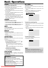
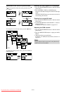
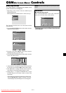
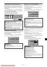
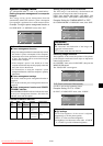
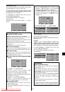
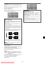
Example: Turning the DISPLAY OSM off
On “OPTION1” menu, select “OSM”, then press the MENU/
ENTER button.
The “OSM” menu appears.
On “DISPLAY OSM” of “OSM” menu, select “OFF”.
SEL. ADJ. RETURN
OSM
EXIT
DISPLAY OSM
OSM ADJ.
OSM ANGLE
OSM ORBITER
OSM CONTRAST
: OFF
: 1
: H
: OFF
: LOW
Information
Ⅵ DISPLAY OSM settings
ON: The informations on screen size, volume control,
etc. will be shown.
OFF: The informations on screen size, volume control,
etc. will not be shown.
The DISPLAY button on the remote control will not
function either.
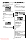
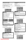
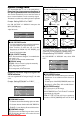
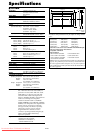
Ⅵ OSM ADJUST settings
Adjusts the position of the menu when it appears on
the screen.
The position can be set between 1 to 6.
Ⅵ OSM ANGLE settings
Sets the display format (landscape “H” or portrait “V”).
When the unit is installed vertically set the OSM
ANGLE at “V”.
“H”“V”
SEL. RETURN
OPTION1 1 / 4
OSM
BNC INPUT
D-SUB INPUT
RGB SELECT
HD SELECT
INPUT SKIP
ALL RESET
NEXT PAGE
: RGB
: RGB
: AUTO
: 1080B
: OFF
: OFF
EXIT
MENU/ENTER
OK
Ⅵ OSM ORBITER settings
ON: The position of the menu will be shifted by eight
dots each time OSM is displayed.
OFF: OSM will be displayed at the same position.
Ⅵ OSM CONTRAST settings
NORMAL: OSM brightness is set to normal.
LOW: OSM brightness is set to lower.
: RGB
: RGB
: AUTO
: 1080B
: OFF
: OFF
1024768
EXIT
SEL.
RETURN
MENU/ENTER
OK
OPTION1
OSM
BNC INPUT
D-SUB INPUT
RGB SELECT
HD SELECT
INPUT SKIP
ALL RESET
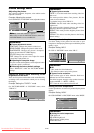
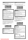
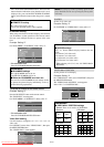
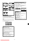
Setting the BNC input connector type
Select whether to set the input of the 5 BNC connectors to
RGB, Component or SCART1,2.
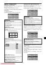
Example: Set the BNC INPUT mode to “COMP.”
On “BNC INPUT” of “OPTION1” menu, select “COMP.”.
SEL. ADJ. RETURN
OPTION1 1 / 4
OSM
BNC INPUT
D-SUB INPUT
RGB SELECT
: AUTO
HD SELECT
INPUT SKIP
ALL RESET
NEXT PAGE
: COMP.
: RGB
: 1080B
: OFF
: OFF
EXIT
Information
Ⅵ BNC INPUT Settings
RGB: Use the 5BNC terminals for RGB input.
COMP.: Use the 3BNC terminals for component input.
SCART1: Use the 4BNC terminals for RGB with
composite sync. See page En-9.
SCART2: Use the 3BNC terminals for RGB and the
VIDEO1 terminal for composite sync. See page En-9.
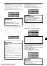
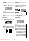
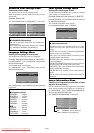
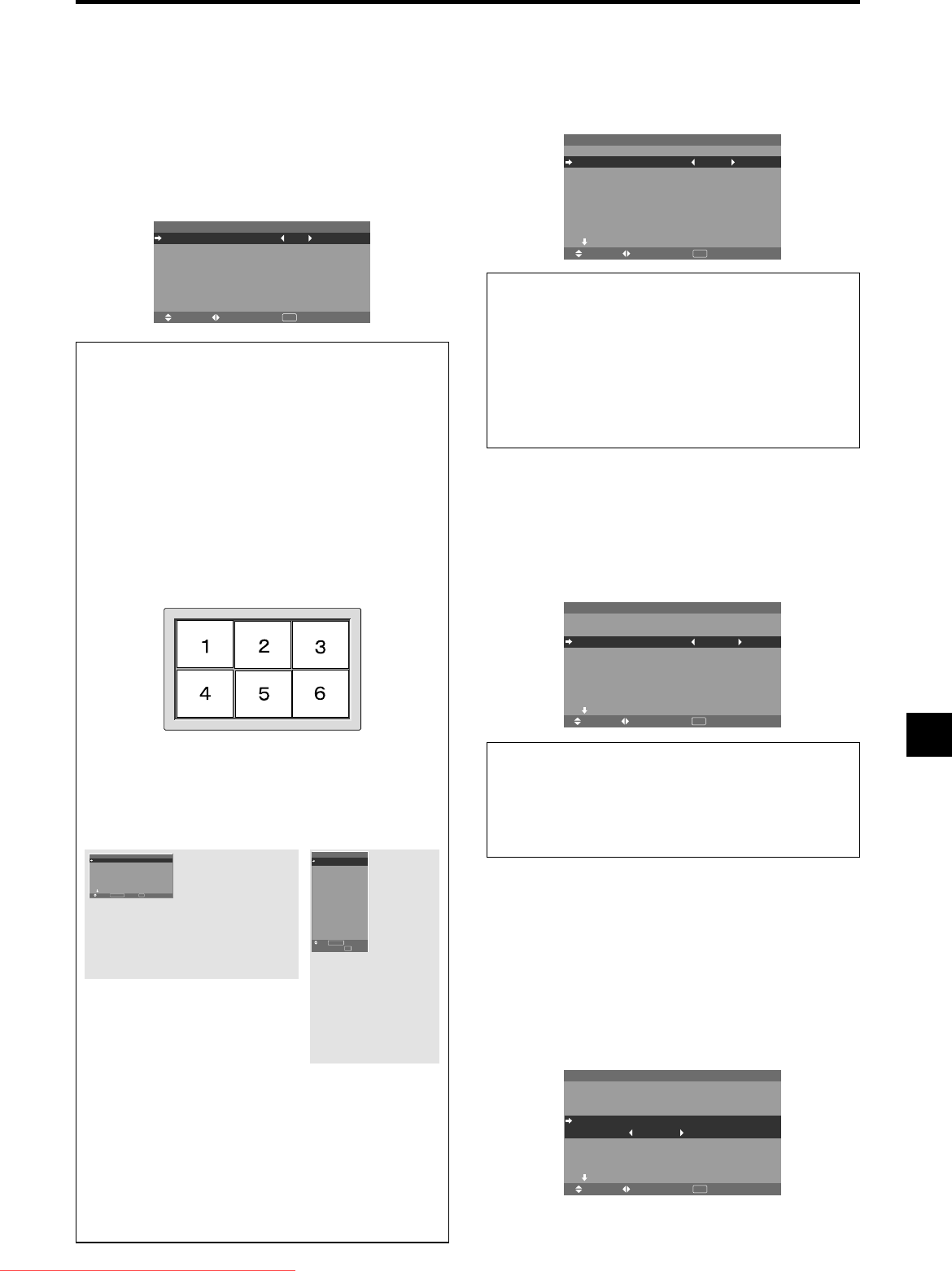
Setting the RGB1 connector
Select one of the signals being transmitted to the RGB1
terminal.
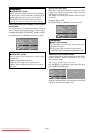
Example: Set the D-SUB INPUT mode to “SCART3”
On “D-SUB INPUT” of “OPTION1” menu, select
“SCART3”.
OPTION1 1 / 4
OSM
BNC INPUT
D-SUB INPUT
RGB SELECT
: AUTO
HD SELECT
INPUT SKIP
ALL RESET
NEXT PAGE
: RGB
: SCART3
: 1080B
: OFF
: OFF
SEL. ADJ. RETURN
EXIT
Information
Ⅵ D-SUB INPUT Settings
RGB: Use the D-SUB terminal for RGB input.
SCART3: Use the D-SUB terminal for RGB signal fed
from SCART. See page En-9.
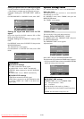
Setting a computer image to the correct RGB
select screen
With the computer image, select the RGB Select mode
for a moving image such as (video) mode, wide mode or
digital broadcast.
Example: Setting the “RGB SELECT” mode to
“852ן480 ”
On “RGB SELECT” of “OPTION1” menu, select
“852ן480”.
SEL. ADJ. RETURN
OPTION1 1 / 4
OSM
BNC INPUT
D-SUB INPUT
RGB SELECT
: 852ן480
HD SELECT
INPUT SKIP
ALL RESET
NEXT PAGE
: RGB
: RGB
: 1080B
: OFF
: OFF
EXIT
Downloaded From TV-Manual.com Manuals