En-31
ID number setting
When using more than one of these displays, this function
sets ID numbers so that operation of the remote control
does not cause multiple monitors to operate at the same
time.
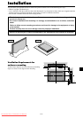
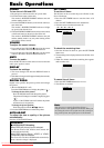
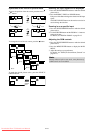
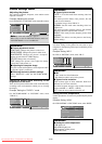
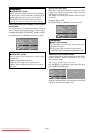
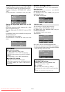
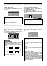
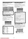
Example: Setting “2”
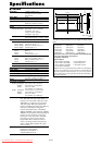
On “ID NUMBER” of “OPTION3” menu, select “2”.
SEL. ADJ. RETURN
OPTION3 3 / 4
PREVIOUS PAGE
TIMER
PWR. ON MODE
CONTROL LOCK
IR REMOTE
LOOP OUT
REMOTE ID
ID NUMBER
VIDEO WALL
NEXT PAGE
: OFF
: ON
: OFF
: ALL
: 2
EXIT
* To reset back to ALL
Press the CLEAR/SEAMLESS SW button
Information
Ⅵ ID NUMBER settings
ALL: ID NUMBER will not be set.
1 to 256: ID NUMBER will be set.
Ⅵ When the ID NUMBER have been set
You can also set ID NUMBER for each remote control
to operate the plasma display individually. To do so,
see the following explanation.
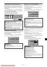
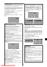
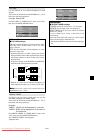
To set the ID number for the remote control
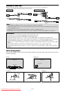
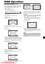
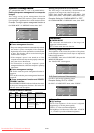
Example: Setting “2”
Press the ID SELECT button on the remote control.
The “ID SELECT” screen appears.
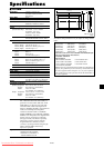
On “ID NUMBER” of “ID SELECT” menu, select “2”.
ADJ. RETURN
EXIT
ID SELECT
POSITION : 1
ID NUMBER
: 2
* To reset back to ALL
Press the CLEAR/SEAMLESS SW button
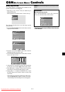
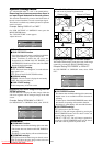
Video Wall setting
Use this feature to configure a (2ן2, 3ן3, 4ן4, 5ן5)
video wall.
On “OPTION3” menu, select “VIDEO WALL”, then press
the MENU/ENTER button.
The “VIDEO WALL” screen appears.
SEL. ADJ. RETURN
VIDEO WALL
DIVIDER
POSITION
DISP. MODE
AUTO ID
IMAGE ADJUST
P. ON DELAY
PLE LINK
REPEAT TIMER
: OFF
: SPLIT
: OFF
: OFF
: OFF
: OFF
EXIT
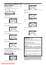
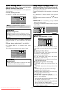
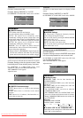
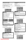
DIVIDER
Set the (2×2) video wall.
Example: Setting “4”
On “DIVIDER” of “VIDEO WALL” menu, select “4”.
SEL. ADJ. RETURN
VIDEO WALL
DIVIDER
POSITION
DISP. MODE
AUTO ID
IMAGE ADJUST
P. ON DELAY
PLE LINK
REPEAT TIMER
: 4
: SPLIT
: OFF
: OFF
: OFF
: OFF
EXIT
Information
Ⅵ DIVIDER settings
OFF, 1: 1 Screen (Matrix display function does not
work)
4: 4 Screens (2×2 video wall)
9: 9 Screens (3×3 video wall)
16: 16 Screens (4×4 video wall)
25: 25 Screens (5×5 video wall)
* When selecting a 2×2, 3×3, 4×4, 5×5 VIDEO WALL
POSITION.
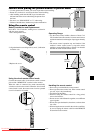
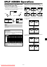
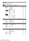
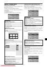
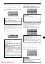
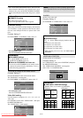
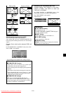
VIDEO WALL POSITION
Set the position of each display.
Example: Setting “4”
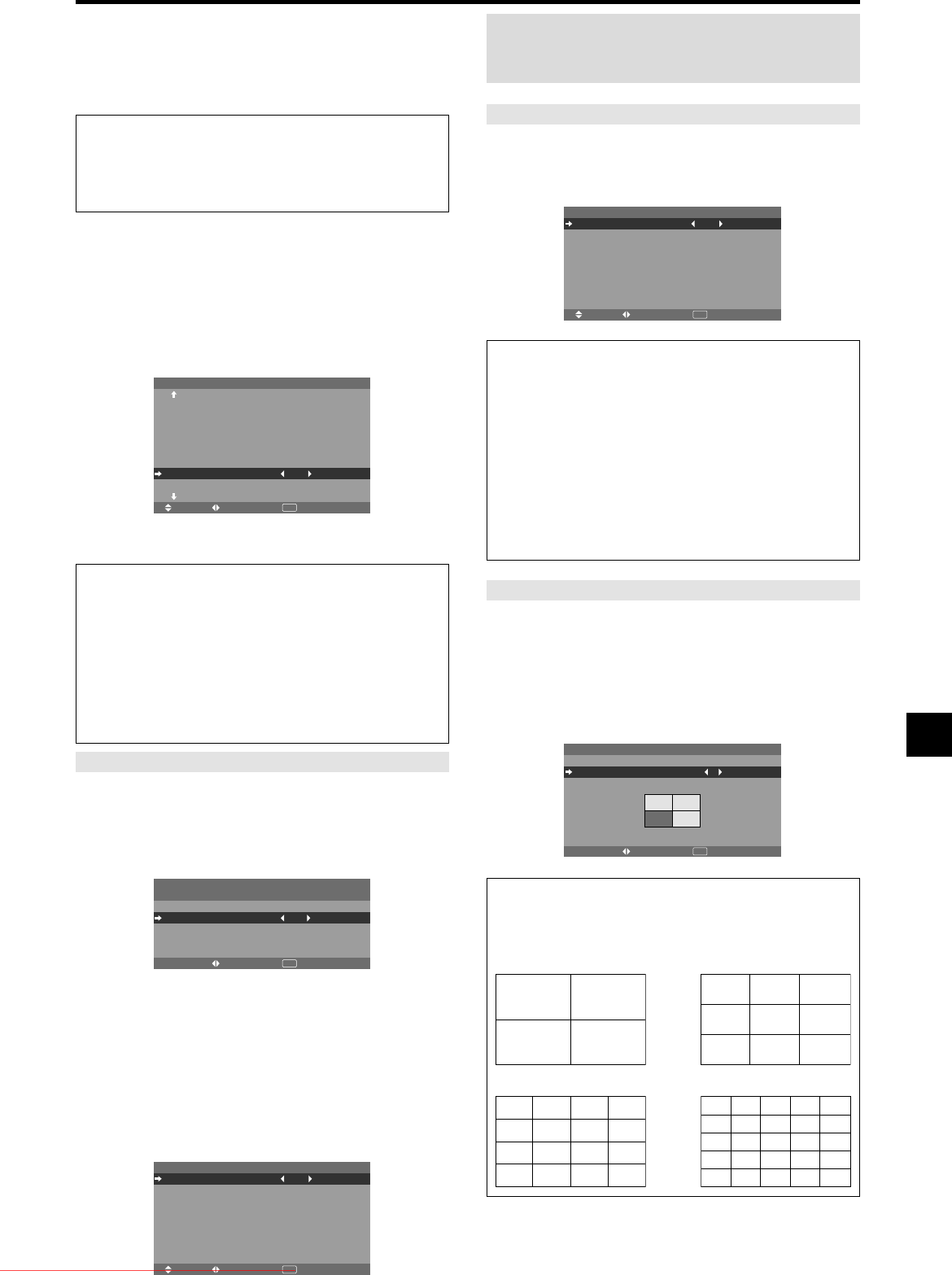
On “VIDEO WALL” menu, select “POSITION”, then press
the MENU/ENTER button.
The “VIDEO WALL POSITION” screen appears.
Select “NO. 4” of “POSITION NO.”.
ADJ. RETURN
VIDEO WALL POSITION
POSITION NO. 4
EXIT
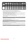
Information
Ⅵ VIDEO WALL POSITION settings
1 Screen: There is no need to set POSITION.
4 Screens 9 Screens
16 Screens 25 Screens
NO. 1
NO. 2
NO. 4
NO. 3
NO. 7
NO. 8
NO. 9
NO. 10
NO. 11
NO. 12
NO. 13
NO. 14
NO. 15
NO. 16 NO. 17 NO. 18 NO. 19
NO. 20 NO. 21 NO. 22 NO. 23
NO. 24 NO. 25 NO. 26 NO. 27
NO. 28 NO. 29 NO. 30 NO. 31
NO. 32 NO. 33 NO. 34 NO. 35 NO. 36
NO. 37 NO. 38 NO. 39 NO. 40 NO. 41
NO. 42 NO. 43 NO. 44 NO. 45 NO.46
NO. 47 NO. 48 NO. 49 NO. 50 NO. 51
NO. 52 NO. 53 NO. 54 NO. 55 NO. 56
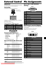
• Press and hold the POWER ON button, and release the
button when the indication saying that the code is set is
displayed. Or, press and hold the POWER STANDBY
button, and release the button when the power is turned
off.
Information
Ⅵ REMOTE ID setting
ALL: The remote code is not set.
1 to 4: The specified remote code is applied.
Note:
A contingency method of shutting off the electric
power should be used in cases of emergency during video
wall setup.
Downloaded From TV-Manual.com Manuals