Chapter 3 Hardware Panels
GS2200-24 User’s Guide
38
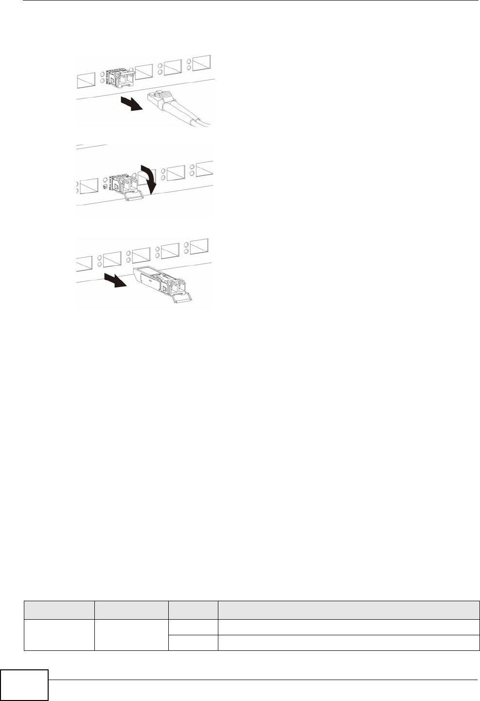
3 Pull the transceiver out of the slot.
Figure 11 Removing the Fiber Optic Cables
Figure 12 Opening the Transceiver’s Latch Example
Figure 13 Transceiver Removal Example
3.2.4 Power Connector
Note: Make sure you are using the correct power source as shown on the panel.
To connect power to the Switch, insert the female end of the power cord to the AC
power receptacle on the front panel. Connect the other end of the supplied power
cord to a power outlet. Make sure that no objects obstruct the airflow of the fans
(located on the side of the unit).
See Chapter 40 on page 333 for information on the Switch’s power supply
requirements.
3.3 LEDs
After you connect the power to the Switch, view the LEDs to ensure proper
functioning of the Switch and as an aid in troubleshooting.
Table 3 LED Descriptions
LED COLOR STATUS DESCRIPTION
PWR Green On The system is turned on.
Off The system is off or has failed.


