


2-4 Receiving & Installation
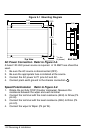
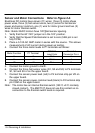
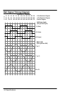
Sensor and Motor Connections Refer to Figure 2-2.
Brushless DC motors have eleven (11) wires: three (3) motor phase
power wires, three (3) hall sensor wires, two (2) wires for hall sensor
power and sensor common, one (1) wire for motor ground and two (2)
wires for motor thermal switch.
Note: Baldor BLDC motors have 120°Hall sensor spacing.
1. Verify that the 60°/120° jumper is in the 120° position.
2. Verify that the Speed Potentiometer is set to zero (5KW pot is set
fully CCW).
3. Place a 0-10A AC AMP meter in series with the source. This allows
measurement of AC current during power up testing.
4. Connect the three motor leads to P1 terminals as follows:
Motor Function P1 Terminal
BSM50A
Lead Color
Threaded
Connector Pin #
U Φ1 Red 1
V Φ3 Black 4
W Φ2 Blue 3
5. Connect the motor ground to Earth.
6. Connect the three hall sensor wires (S1, S2 and S3) to P4 terminals
S1, S2 and S3 of on the upper board.
7. Connect the sensor power lead (red) to P4 terminal strip pin VR on
the upper board.
8. Connect the sensor power common lead (black) to P4 terminal strip
pin COM on the upper board.
Note: The motor has an internal thermal switch (155°C ±5°C normally
closed contact). The BSC7107 does not use this contact so no
connection to the thermal switch leads is required.