


SKU 93801/93802 For technical questions, please call 1-800-444-3353. PAGE 6
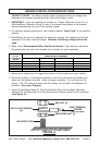
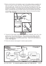
10.Mount a circuit breaker (not included) as near to the auxiliary battery as possible, but
away from engine or exhaust heat (See
“Recommended Wire Size/Circuit Breaker”
Chart for proper size). Connect one end of a new wire of the proper size to the “2”
terminal of the Isolator. Run the wire to the circuit breaker and connect it to the “AUX”
terminal or its equivalent. Run another wire from the circuit breaker to the auxiliary
battery, connecting one end to the “BAT” terminal of the circuit breaker and the other
to the positive (+) terminal of the auxiliary battery. Repeat for three and four battery
isolators. (See Figure D.)
FIGURE D
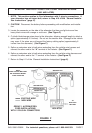
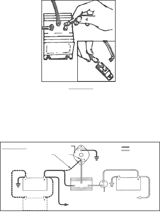
11. Connect all of the auxiliary loads (phone, lights, stereo, refrigerator, winch, etc.) to the
positive post of the auxiliary battery(ies). Reconnect the ground cables removed in
Step #5. Also, make sure the negative (–) terminal of the auxiliary battery(ies) are
properly grounded with a conventional ground strap. Protect with circuit breakers as
needed. (See Figure E.)
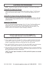
12. Perform the electrical tests (page 8) to assure proper operation.
A
1
2
AUX.
BATTERY
ALTERNATOR
OUTPUT
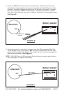
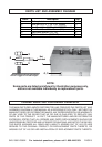
REMOVE ORIGINAL WIRE(S)
FROM ALTERNATOR.
PLACE ON TERMINAL #1 OF ISOLATOR.
BATTERY #1
VEHICLE
BATTERY #2
AUXILIARY
A
12
CIRCUIT
BREAKER
TO AUXILIARY EQUIPMENT:
STEREO, LIGHTS, REFRIGERATOR,
WINCH, ETC.
TO VEHICLE IGNITION
SYSTEM, HEADLIGHTS,
HORN, ETC.
SECOND MAIN
BATTERY USED ON
MANY VEHICLES
ISOLATOR
EXISTING WIRE
NEW WIRE
FIGURE E