


SKU 93801/93802 For technical questions, please call 1-800-444-3353. PAGE 8
ELECTRICAL TEST PROCEDURES
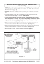
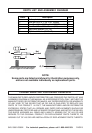
1. NOTE: Connect the negative test lead to the negative (–) terminal on the battery.
Testing With The Engine Not Running:
The #1 terminal of the Isolator should read vehicle battery voltage. The #2 terminal
should read auxiliary battery voltage. The “A” terminal may read from zero to 13
volts.
Testing With The Engine Running And Alternator Charging:
The #1 and #2 should read regulator setting or less, typically from 13.8 to 14.5 volts.
The “A” terminal voltage should read 0.8 to 1 volt higher than the reading of the #1
and #2 terminals.
Testing For 12 Volt Systems:
The “A” post should read approximately 14.8 to 15.5 volts. The #1 and #2 terminal
should read 13.8 to 14.5 volts. If the “A” terminal reads 13.8 to 14.2 volts the
regulator may be sensing the alternator output rather than the main battery. This
situation needs to be corrected for proper charging of batteries.
TESTING THE ISOLATOR WITH AN OHMMETER**
**If using a digital ohmmeter, a diode scale MUST be used.
1. Remove all wires from the Isolator.
2. Using a needle movement ohmmeter, Rx-1 scale, or a digital ohmmeter diode scale,
hold the RED* probe on terminal “A” and with the BLACK* probe touch terminal #1
and #2. A good Isolator will show a current flow from “A” to #1 and #2.
3. Next, hold the BLACK* probe on terminal “A” and with the RED* probe touch terminal
#1 and #2. A good Isolator will allow no current flow from “A” to #1 and #2.
4. Hold one probe on the aluminum heatsink, making sure there is contact by scratching
through the protective coating. Then touch with the other probe terminals “A”, #1, and
#2. A good Isolator will show no current flow.
*NOTE: On some import ohmmeters, the RED and BLACK probes are reversed
for these tests.