


SKU 93801/93802 For technical questions, please call 1-800-444-3353. PAGE 7
SPECIAL INSTRUCTIONS FOR FORD INSTALLATIONS
(1985 AND LATER)
1. NOTE: This section applies to Ford alternators with 2 plug-in connections. If
your alternator has an output bolt, return to Step #10 of the
“General Installa-
tion Instructions”
(page 6).
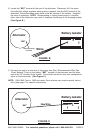
2. CAUTION! Disconnect the battery before proceeding with modification and installa-
tion.
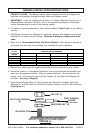
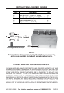
3. Locate the connector on the side of the alternator that has one light wire and two
heavy black wires with orange or red trace. (See Figure F.)
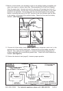
4. Cut both black/orange wires close to the alternator, allowing enough length to attach a
splice (approximately 2-3 inches). Do not cut the smaller wire. Damage to the vehicle
may occur if the wires are cut beyond the factory cabling splice (approximately 6
inches from the alternator). (See Figure F.)
5. Splice an extension wire to both wires extending from the vehicle wire harness and
connect the other end to the “A” terminal of the Isolator. (See Figure F.)
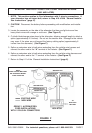
6. Splice an extension wire to both wires extending from the vehicle wiring harness and
connect the other end to the “1” terminal of the Isolator. (See Figure F.)
7. Return to Step #11 of the
“General Installation Instructions”
(page 6).
ORANGE/BLACKORANGE/BLACK
WHITE/BLACK
NOTE:
WIRE COLORS MAY VARY
ON DIFFERENT MODEL
FORD VEHICLES
RED/BLACK
RED/BLACK
WHITE/BLACK
ORANGE/BLACK
RED/BLACK
EXISTING WIRE
NEW WIRE
GROUP 1 ALTERNATORS:
FORD INSTALLATIONS
WITH 2 PLUG-IN CONNECTORS
TO
AUXILIARY
BATTERY
ISOLATOR
FIGURE F