2-4
Catalyst Switch Module 3110G, 3110X, and 3012 for IBM BladeCenter Hardware Installation Guide
OL-12192-01
Chapter 2 Switch Module Installation
Installing the Switch Module
Installing the Switch Module
This section covers switch module installation. The illustrations in this section show the Catalyst Switch
Module 3110G. The instructions are the same for the Catalyst Switch Module 3110X and 3012.
Follow these steps:
Step 1 Remove the acoustic attenuation module, if one is installed, from the rear of the blade enclosure.
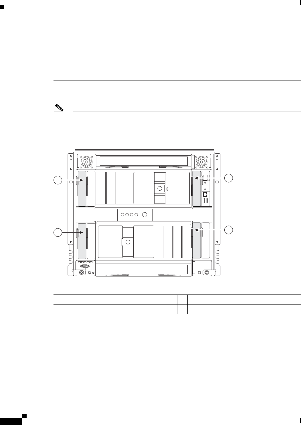
Step 2 Select the blade enclosure bay in which to install the switch module (Figure 2-1).
Note Figure 2-1 shows the IBM BC-H blade enclosure as an example. Your blade enclosure might
look different.
Figure 2-1 Blade Enclosure Rear-Panel View
Step 3 Remove the filler module from the selected bay. Store the filler module for future use.
Step 4 If you have not already done so, touch the static-protective package that contains the switch module to
any unpainted metal surface of the blade enclosure or any unpainted metal surface on any other grounded
rack component for at least 2 seconds.
Step 5 Remove the switch module from its static-protective package.
Step 6 Move the switch module release latch to the open position (perpendicular to the switch module).
1 I/O module bay 1 3 I/O module bay 3
2 I/O module bay 2 4 I/O module bay 4
270428
1
3
4
2
