


B-5
Catalyst Switch Module 3110G, 3110X, and 3012 for IBM BladeCenter Hardware Installation Guide
OL-12192-01
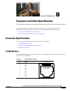
Appendix B Connector and Cable Specifications
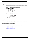
Cable and Adapter Specifications
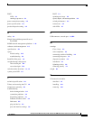
Two Twisted-Pair Cable Pinouts
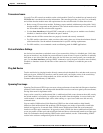
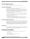
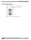
Figure B-6 and Figure B-7 show the schematics of two twisted-pair cables.
Figure B-6 Two Twisted-Pair Straight-Through Cable Schematic
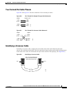
Figure B-7 Two Twisted-Pair Crossover Cable Schematic
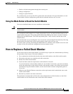
Identifying a Crossover Cable
To identify a crossover cable, compare the two modular ends of the cable. Hold the cable ends
side-by-side, with the tab at the back. The wire connected to the pin on the outside of the left plug should
be the same color as the wire connected to the pin on the outside of the right plug. (See
Figure B-8.)
Figure B-8 Identifying a Crossover Cable
Switch
3 TD+
6 TD–
1 RD+
2 RD–
Router or PC
3 RD+
6 RD–
1 TD+
2 TD–
H5578
Switch
3 TD+
6 TD–
1 RD+
2 RD–
Switch
3 TD+
6 TD–
1 RD+
2 RD–
H5579
Pin 1
H10632
Pin 8
Pin 1 on one connector and
pin 8 on the other connector
should be the same color.