3-15
Cisco UCS C420 Server Installation and Service Guide
OL-27640-01
Chapter 3 Maintaining the Server
Installing or Replacing Server Components
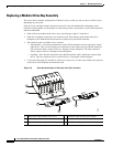
To install or replace the modular drive bay assembly, follow these steps:
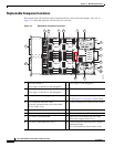
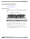
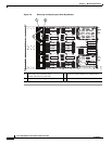
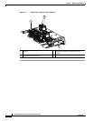
Step 1 Remove the assembly that you are replacing. See Figure 3-8 and Figure 3-9:
a. Power off the server as described in Shutting Down and Powering Off the Server, page 3-8.
b. Slide the server out the front of the rack far enough so that you can remove the top cover. You might
have to detach cables from the rear panel to provide clearance.
Caution If you cannot safely view and access the component, remove the server from the rack.
c. Remove the top cover as described in Removing and Replacing the Server Top Cover, page 3-9.
d. Remove all drives from the drive-bay module that you are replacing.
e. Remove the fan tray from the chassis, as described in Replacing a Fan Tray, page 3-19. You do not
have to remove the fan modules from the fan tray.
f. Disconnect RAID controller cables from the transition card that you are replacing.
Tip Label the cables before you disconnect them to aid replacement.
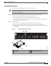
g. Use a Number 2 Phillips screwdriver to remove the two screws that secure the transition card to the
chassis floor (see Figure 3-9).
h. Slide the drive bay with the attached backplane and transition card out the front of the chassis. The
transition card disengages from its motherboard connector.
Note Tilt the module downward as you slide it out the chassis opening to provide clearance over an
alignment peg on the chassis floor.
Step 2 Install a new drive bay assembly:
a. Carefully slide the drive bay with the attached backplane and transition card into the front chassis
opening.
Stop when the connector on the rear edge of the transition card is fully engaged with the
motherboard connector and the front of the drive bay is even with the chassis front panel.
b. Replace the two screws that secure the transition card to the chassis floor.
c. Replace the RAID controller cables to the connectors on the transition card.
d. Replace the fan tray as described in Replacing a Fan Tray, page 3-19.
e. Replace the top cover.
f. Replace the server in the rack, replace cables, and then power on the server by pressing the Power
button.


